
M540 telemetry system
Digital telemetry system for one to three strain gage bridge or thermocouple channels, with a 14-bit transmitter weighing 12 g and a ±10 V analog receiver.
- 1 to 3
- Channels
- 14 bit
- Resolution
- DC to 5 kHz
- Data bandwidth, one channel
- 12 g
- Transmitter weight
- InputsStrain gage bridge or thermocouple
- Output±10 V analog
- Power supplyBattery or induction
- Transmitter temperature−40 to 125 °C
One to three channels, 14-bit transmitter
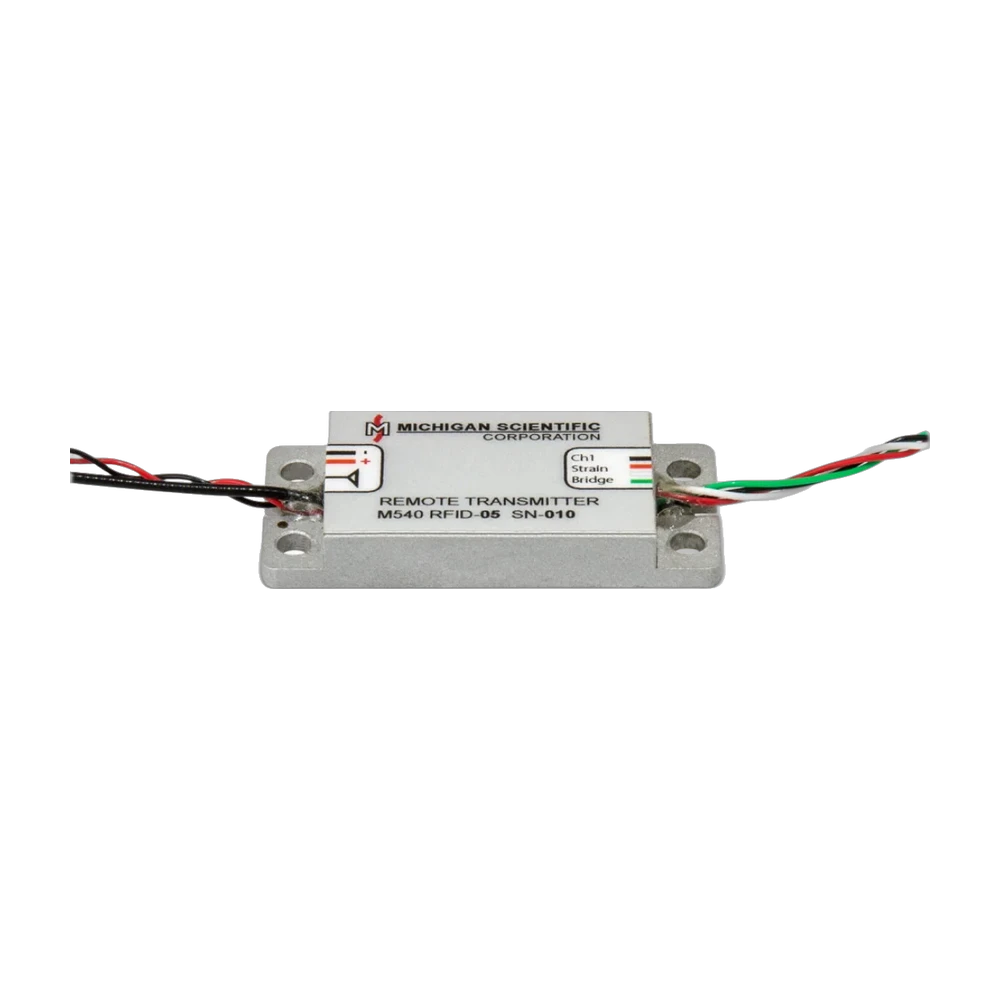
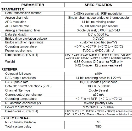
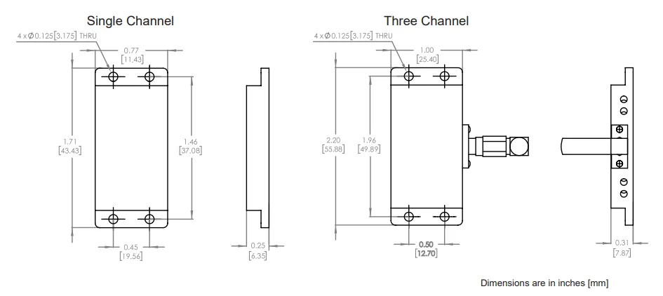
The Series M540 is a digital telemetry system for one to three strain gage bridges or thermocouples. Its transmitter has a strain gage driver with 3.0 V excitation and its own gain and shunt resistor, then a fully differential amplifier and an anti-aliasing filter ahead of a 14-bit converter. Data bandwidth is DC to 5 kHz on one channel and DC to 2.5 kHz on three. The one-channel transmitter measures 43.4 × 19.6 × 6.4 mm, the three-channel one 55.9 × 25.4 × 7.9 mm; it weighs 12 g and runs from −40 to 125 °C.
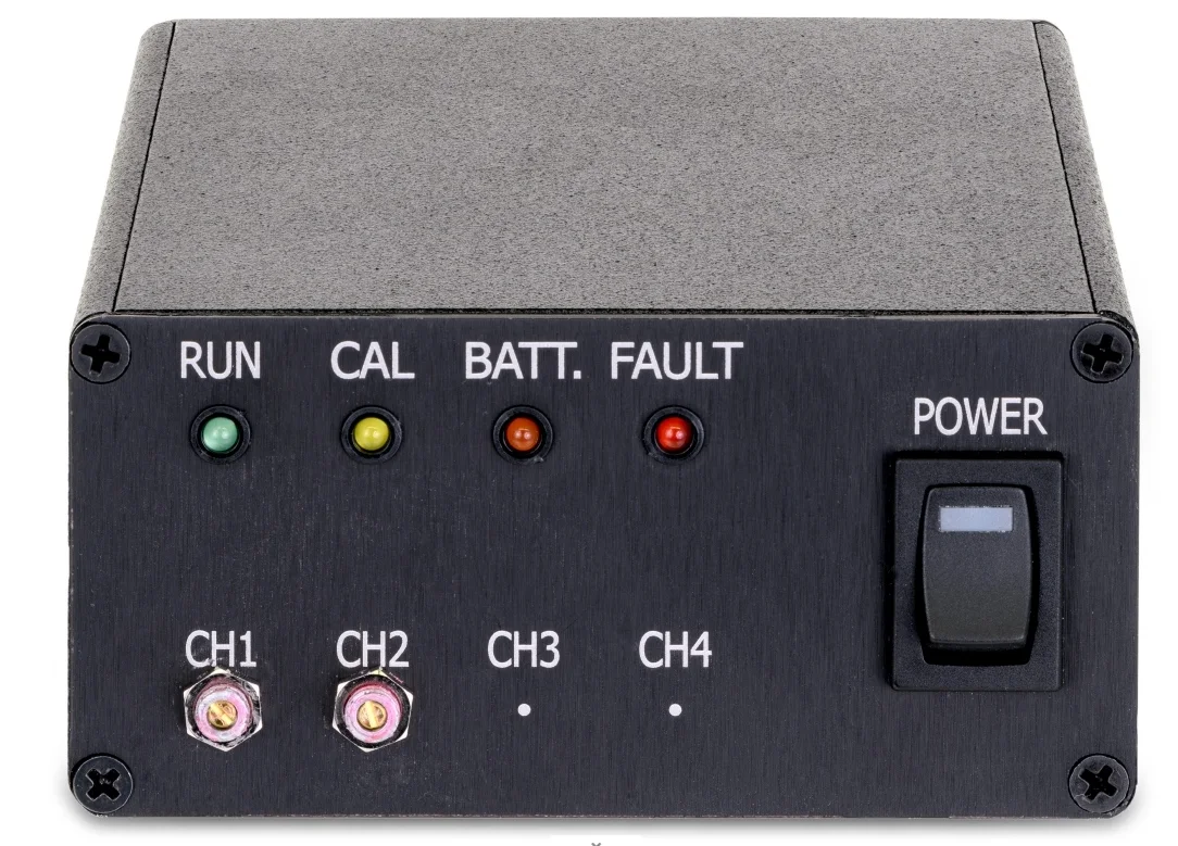
The transmitter fixes through four mounting holes and takes 6 to 9 V DC, from a battery or by induction. Data goes out on a 2.4 GHz link, with 16 RF channels. The receiver runs on 9 to 36 V DC and takes two antennas; RF diversity and error checking guard against reflections and shadowed transmissions. It gives ±10 V outputs on a rear connector, with 100 Hz or 5 kHz filter cutoffs and optional zero offset adjustment. Front-panel LEDs and status outputs report transmission quality, low power and shunt status.
It is used for measurements on rotating equipment and wherever a wired sensor cannot reach. The M540 transmitter is also the one built into the CBT-mini clamp-on transmitter and the T3 end-of-shaft telemetry.
Specifications
| Channels | 1 to 3 |
|---|---|
| Input | Strain gage bridge · Thermocouple |
| Output | Analog voltage |
| Output range | −10 to 10 V |
| Bandwidth | 5 kHz (one channel; 2.5 kHz with three channels; receiver filter 100 Hz or 5 kHz (−3 dB, 2-pole Bessel)) |
| Sample rate | 15 kHz (receiver DAC updates) |
| Resolution | 14 bit (no missing codes) |
| Gain setting | Customer specified |
| Output current | 35 mA |
| Analog output resolution | 14 bit |
| RF band | 2.4 GHz (FSK modulation; medium to short range) |
| RF channels | 16 |
| Supply voltage | 9 to 36 V (receiver; transmitter 6 to 9 V DC, 65 mA) |
| Power source | Battery · Induction |
| Excitation voltage | 3 V |
| Supply current | 500 mA (receiver) |
| Dimensions | 43.4 × 19.6 × 6.4 mm (transmitter, one channel; three channels 55.9 × 25.4 × 7.9 mm) |
| Weight | 12 g (transmitter) |
| Dimensions, stationary electronics | 180 × 89 × 38 mm (receiver; 64 mm high with induction) |
| Operating temperature | −40 to 125 °C |
| Protection | Environmentally sealed (rugged) |
| Operating temperature, stationary electronics | −40 to 70 °C |
| Connector | Reverse-polarity SMA (2 antenna connectors) |
Request a quote
Resources
Datasheets and manuals
Drawings
None for this product.
CAD models
None for this product.
Guides and notes
Related applications
-
 Efficiency Vehicle efficiency and power mapping Torque and speed measured at each driveline stage, from engine to wheel, so each power loss has a location.
-
 Powertrain Truck solid axle torque Drive torque on a truck solid axle, read by strain gages inside the shaft and brought out at the wheel.
-
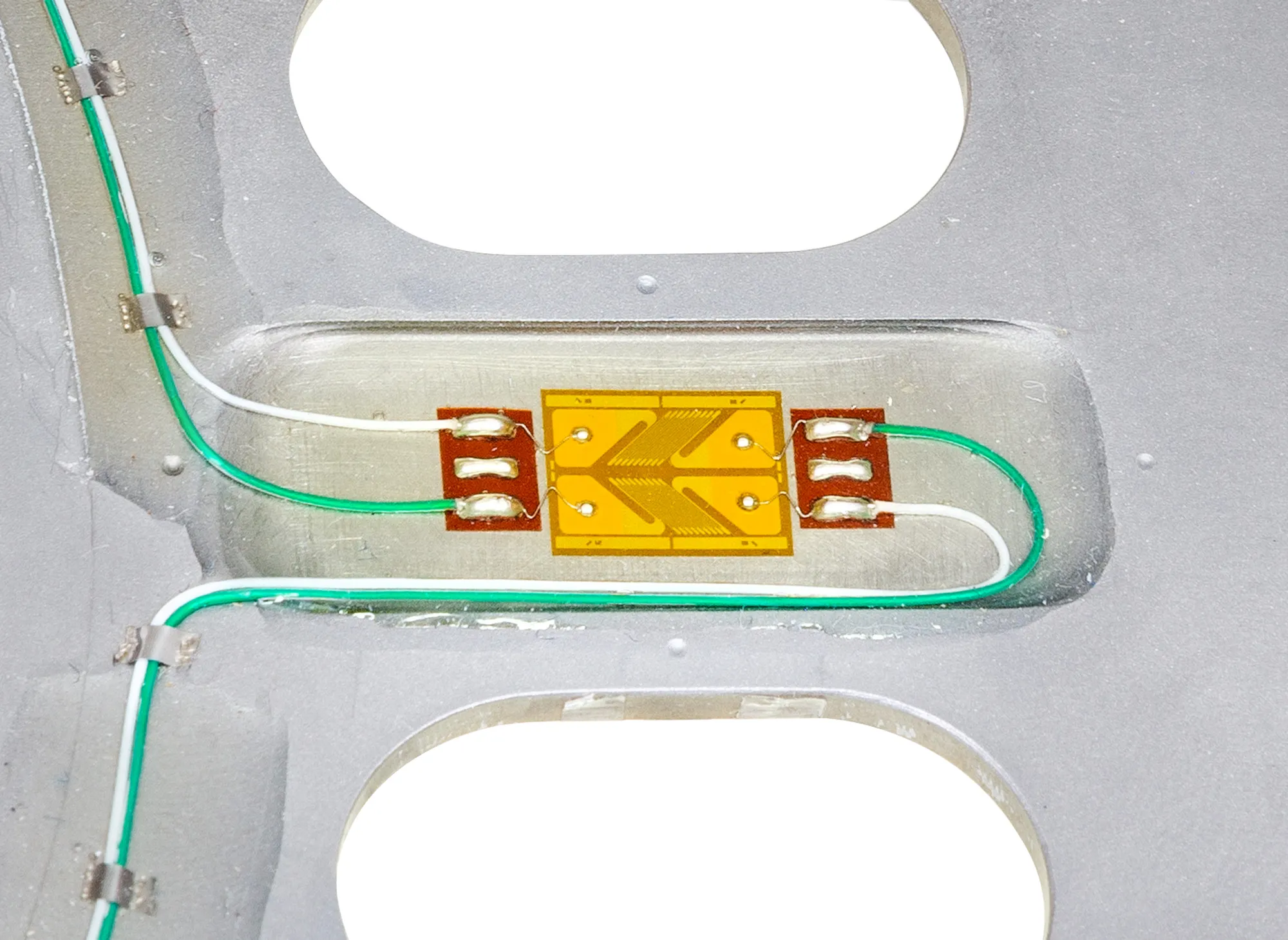 Engine Crankshaft measurements Torque, bending and strain on the production crankshaft with the engine running, in the vehicle or on the dyno.
-
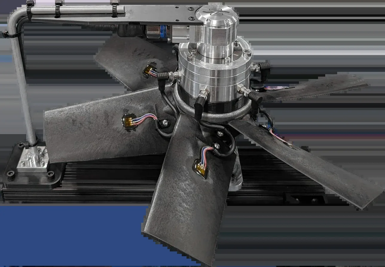 Turbines Fan and turbine blades Strain and temperature from many points on the blades, recorded together while the rotor turns.
In the same family
- Three channels M320
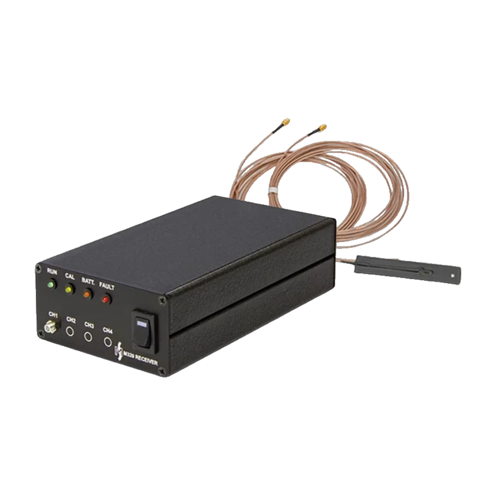
Digital telemetry system for up to three strain gage bridge or thermocouple channels, 12-bit at 3 kHz, with a 38.1 × 40.6 × 8.9 mm transmitter weighing 25 g.
- 16-bit resolution M460
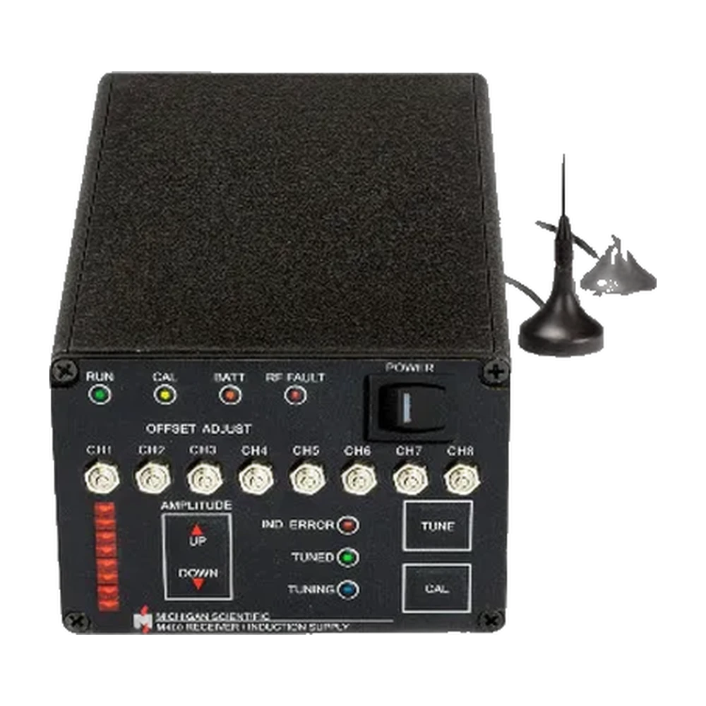
Digital telemetry system for one to eight full strain gage bridges or thermocouples, sampled simultaneously at 16 bits, with ±10 V analog outputs or Ethernet data to a PC.
- Clamp-on, on a shaft CIT
Induction-powered clamp-on telemetry transmitter for one or two full strain gage bridges, in an IP67 housing strapped to shafts of 25 mm or more, with a 2.4 GHz digital link.
A question on this product?
Describe the measurement. An application engineer answers.
More details to give? Use the full contact form.