
Measuring the forces at the seat mountings without changing the driving position
In brief
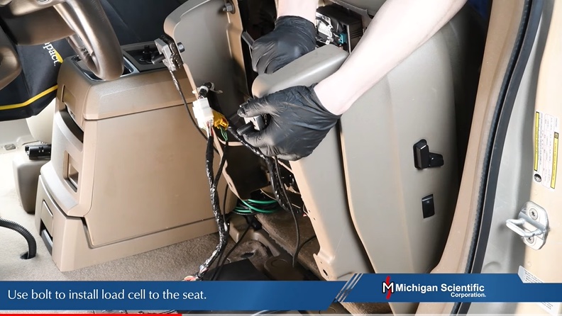
A TR3D three-axis load cell is bolted between the seat and each of its mountings. It reads the longitudinal, lateral and vertical forces at that mounting while driving and in a crash test. The load cell takes the mounting moments and is low enough to leave the seat at its production height. One SGA12A amplifier box excites and amplifies the four load cells of a seat.
- 3
- forces per mounting, Fx, Fy, Fz
- 1.1 to 444 kN
- capacity per axis, TR3D series
- 4
- three-axis load cells on one SGA12A box
Load path
The occupant's load goes from the seat frame into the floor through the seat mountings. Each mounting carries a longitudinal force Fx, a lateral force Fy and a vertical force Fz, plus the moments due to the offset between the seat frame and the fastener. The sizing of the mountings is validated in the two load cases that govern it: driving, and crash.
The load cell is placed in this load path, between the seat and the mounting. A load cell that raised the seat would change the driving position, and with it the load case.
Load cell
The TR3D measures three perpendicular forces in one body and has a rated maximum moment per axis. It is bolted to the seat, then the seat is refitted on its mountings. Capacity, body shape and height are chosen for the vehicle and the room under the seat.
| Models | TR3D-A round · TR3D-B square · TR3D-C and TR3D-D, 44 to 444 kN |
|---|---|
| Capacity per axis | 1.1 kN (TR3D-B-250, 25.4 × 25.4 × 12.7 mm) to 444 kN (TR3D-D-100K) |
| Moments | rated maximum moment per axis, taken by the load cell |
| Non-linearity | < ± 0.5 % FSO on the TR3D-A and TR3D-B |
| Cable | length to order |
Signal conditioning
Each load cell has three strain gage bridges. An SGA12A amplifier box has twelve channels, the four three-axis load cells of one seat. It supplies the bridge excitation, ± 5 V or ± 2.5 V, from its own power supply, outputs ± 10 V DC per channel, and has remote shunt calibration for span verification before the run.
Procedure
- 01
Select the load cell
By capacity per axis, maximum moment and height available under the seat.
TR3D three-axis load cells - 02
Bolt the load cell to the seat
One per mounting. The seat goes back on its mountings through the load cells.
- 03
Connect the amplifier box
Twelve bridge inputs, ± 10 V DC per channel to the data acquisition system.
SGA12A amplifier box - 04
Shunt calibration
Remote shunt calibration on each channel verifies the span before the run.
Result
Fx, Fy and Fz at each seat mounting, while driving or in a crash test, with the seat at its production height. The data validates the sizing of the mountings.
Frequent questions
Where are the load cells placed to measure seat forces?
Between the seat and each mounting. The load cell is bolted to the seat, then the seat is refitted on its mountings.
How many load cells and amplifier channels does one seat need?
One three-axis load cell per mounting, four per seat: twelve bridges, one SGA12A amplifier box.
Do the load cells change the driving position?
The load cell is chosen for its height under the seat. The TR3D-B-250 body is 25.4 × 25.4 × 12.7 mm.
Which load cell is used for seat force measurements?
A TR3D three-axis load cell, round TR3D-A or square TR3D-B, C or D, chosen by capacity, moment and room under the seat. The series covers 1.1 to 444 kN per axis.
Similar applications
All applications-
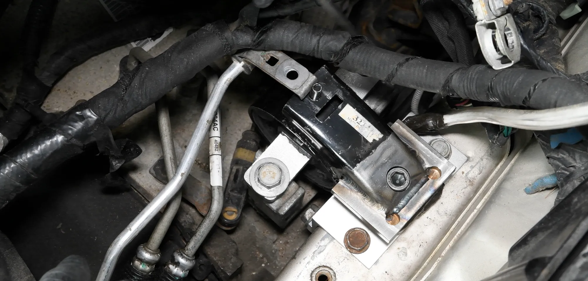 Component Engine mount loads The three forces each mount passes to the frame during start-up, acceleration and gear shifts.
-
 Suspension Suspension component loads How the wheel loads split between the suspension components and enter the chassis.
-
 Durability Durability campaigns The load each wheel really sees on a pothole, an obstacle or a rough track, as recorded data.