
Measuring the forces and moments at each wheel during braking and cornering
In brief
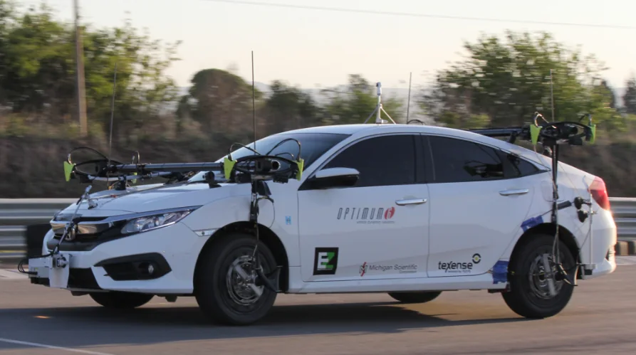
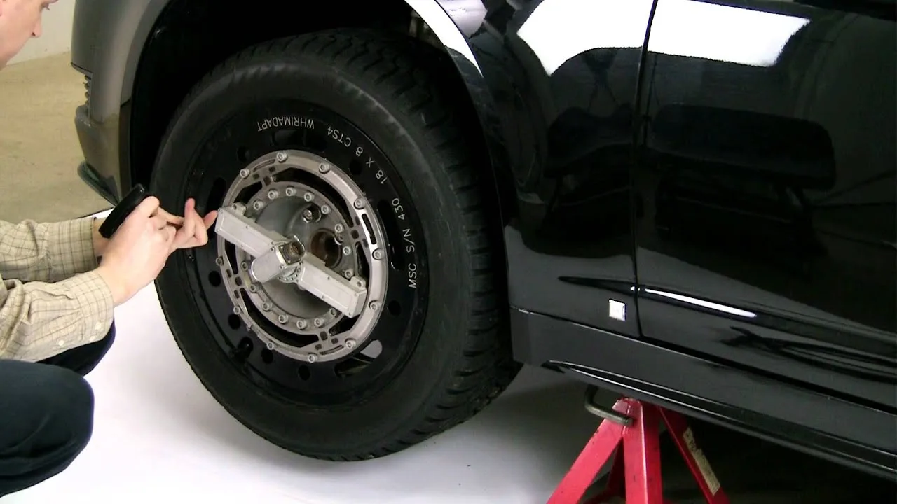
A wheel force transducer replaces the wheel center and measures the longitudinal, lateral and vertical force at that wheel, the camber moment, the wheel torque and the steer torque, each as an independent signal, with the wheel angle, the wheel speed and the X and Z accelerations. The signals are digitized on the wheel, leave it through a slip ring or by telemetry, and the CT2 interface box resolves them into vehicle axes in real time. With one transducer per wheel, a brake test, a lane change or a sharp turn is read wheel by wheel.
- 6
- independent load signals per wheel
- 15.5 to 700 kN
- radial force capacity, LW series
- 0.17°
- angular resolution of the wheel angle, slip ring versions
Six loads at the wheel
Longitudinal forces, along the vehicle, serve the analysis of acceleration, braking and fuel consumption. Lateral forces, across the vehicle, serve cornering, handling and stability. Vertical forces, from gravity and the ground, serve ride comfort, vibration and road contact. The three moments, roll, pitch and yaw, show how the suspension reacts to turns, accelerations and road conditions.
All these loads reach the vehicle through its wheels, on a part that rotates and steers. The transducer measures the six components at the wheel center, separately from one another, and the interface box expresses them in the axes of the vehicle with the wheel angle at every instant.
Instrumentation
| Transducer | LW series, four-arm strain gage bridges, one independent signal per component |
|---|---|
| Capacity, radial | 15.5 to 700 kN · 50 kN on the LW12.8-50 and 65 kN on the LW65 for passenger cars and SUVs |
| Non-linearity | ≤ 0.2 % FS on Fx, Fz and My (LW12.8-50) · cross-axis sensitivity after correction < 0.5 % FS |
| Also measured | wheel angle at 0.17° resolution, wheel speed, X and Z acceleration |
| Mounting | between a hub adapter and a rim adapter made for the vehicle; the stator held by a restraint rod, or by the stator angle correction device on steered wheels |
| Signal transmission | slip ring with spinning amplifier, or telemetry; swappable on the same transducer |
| Interface box | CT2: coordinate transformation and crosstalk compensation in real time, analog, CAN and Ethernet outputs |
| Environment | weatherproof, temperature compensated, −40 to 125 °C; IP67 on the LW65 |
Procedure
- 01
Fit the transducer in place of the wheel center
The transducer mounts between a hub adapter and a rim adapter made for the vehicle.
LW series wheel force transducers - 02
Hold the stator
On a steered wheel, the stator angle correction device corrects the wheel angle in real time, so the loads are resolved with the right angle.
Stator restraint and angle correction - 03
Resolve the loads in the interface box
The CT2 box does the coordinate transformation and the crosstalk compensation in real time, with analog, CAN and Ethernet outputs.
- 04
Add the side slip angle if needed
The TrueSlip optical sensor, on a wheel or on the body, gives the side slip angle on CAN. It can be mounted within the wheel force transducer assembly.
TrueSlip side slip sensor
Double lane change on a class 8 truck
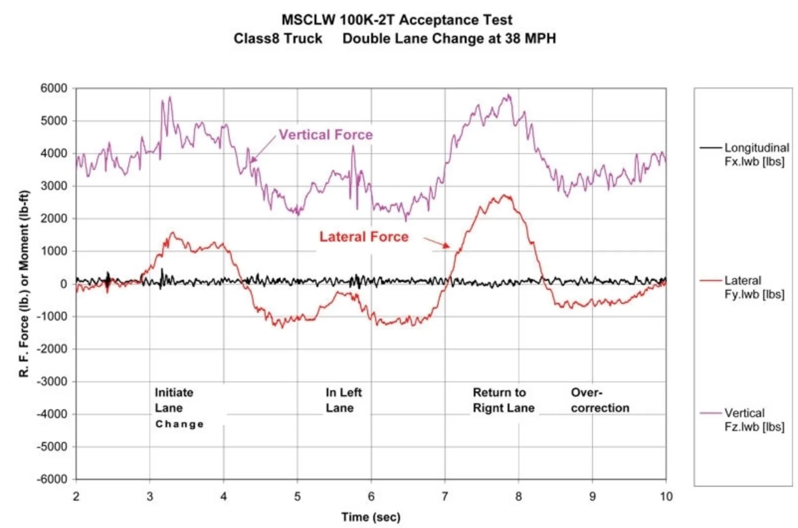
The same setup records brake tests, lane changes, sharp turns and normal driving. In this acceptance test on a class 8 truck, the right front wheel carries an LW-2T-100K. The lateral force rises as the truck leaves its lane, reverses as it returns, and the chart notes an over-correction at the end of the manoeuvre; the vertical force is recorded alongside.
Use of the data
Wheel force data is used in work on tires, brakes, suspension, comfort, aerodynamics, powertrain and vehicle dynamics models, and to compare vehicles with one another. On electric vehicles it serves efficiency work, and it feeds the development of the safety and control functions and of autonomous driving.
Result
Three forces, three moments, wheel speed and angle at each wheel, in vehicle axes, recorded through the manoeuvre. Each behaviour of the vehicle, from braking to cornering, is read in the loads at the wheels that produce it.
Frequent questions
What does a wheel force transducer measure in a vehicle dynamics test?
The longitudinal, lateral and vertical force at the wheel, the camber moment, the wheel torque and the steer torque, each as an independent signal, with the wheel angle, the wheel speed and the X and Z acceleration.
How is the side slip angle measured during a handling test?
With the TrueSlip optical sensor mounted on a wheel or on the vehicle body. It can be mounted within the wheel force transducer assembly and outputs the angle on CAN.
Can wheel forces be measured on a wet track?
Yes. The transducers are weatherproof and temperature compensated, and the LW65 is rated IP67.
How do the signals get from a rotating wheel to the data recorder?
They are digitized on the wheel, leave it through a slip ring or a telemetry link, and reach the CT2 interface box, which does the coordinate transformation and the crosstalk compensation in real time, with analog, CAN and Ethernet outputs.
Similar applications
All applications-
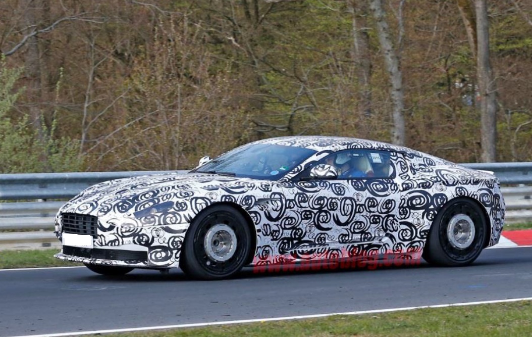 Durability Wheel loads on the road Three forces and three moments at each wheel, recorded while the vehicle is driven.
-
 Winter Winter testing Wheel forces and wheel speed measured on snow and ice, to see the moment a tire starts to slip.
-
 Tires Tire-road friction Tire and road surface forces measured in three directions on a traction fixture, to find the coefficient of friction.