
CIT clamp-on induction telemetry
Induction-powered clamp-on telemetry transmitter for one or two full strain gage bridges, in an IP67 housing strapped to shafts of 25 mm or more, with a 2.4 GHz digital link.
- 1 or 2
- Strain gage channels
- 25 mm
- Min shaft diameter
- Induction
- Power supply
- −40 to 85 °C
- Operating temperature
- Output±10 V analog
- GainProgrammable (M320) or fixed (M540)
- HousingIP67
- Transmitter size53 × 53 × 27 mm
One or two bridges, powered by induction
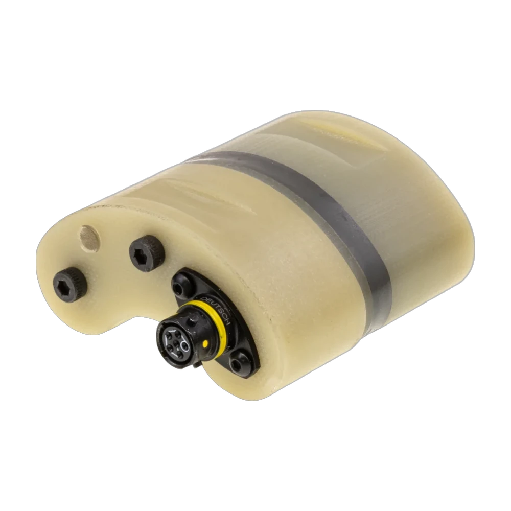
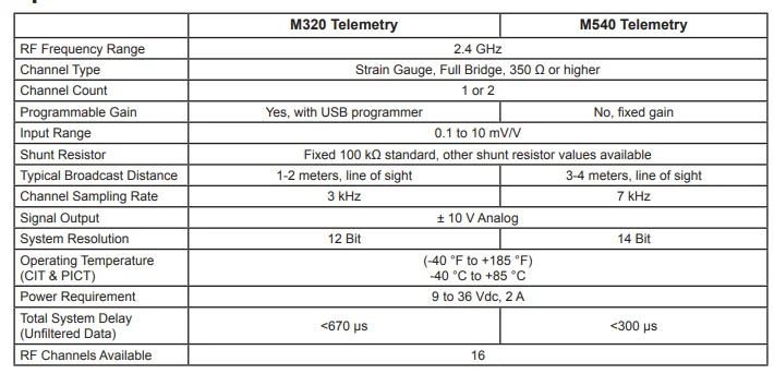
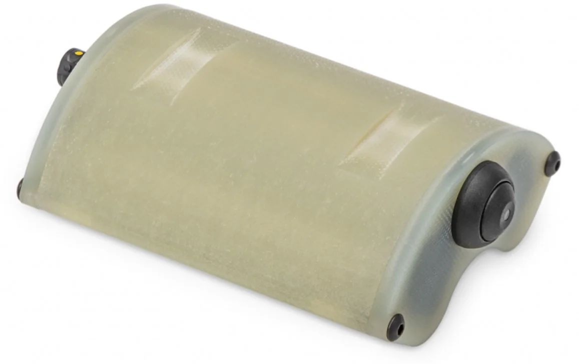
The CIT is a wireless transmitter for one or two full strain gage bridges of 350 Ω or more, with an input range of 0.1 to 10 mV/V, powered without batteries by a stationary primary induction coil (PICT). It excites the bridges and transmits the signals digitally on a 2.4 GHz link with error checking. With M320 telemetry the gain is programmable over USB, at 3 kHz and 12 bits; with M540 telemetry the gain is fixed, at 7 kHz and 14 bits. The output is ±10 V; the IP67 housing measures 53 × 53 × 27 mm and runs from −40 to 85 °C.
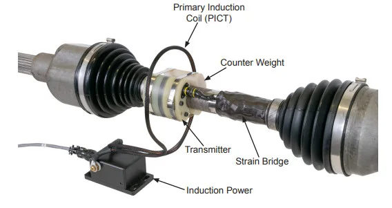
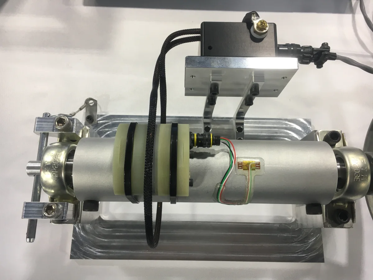
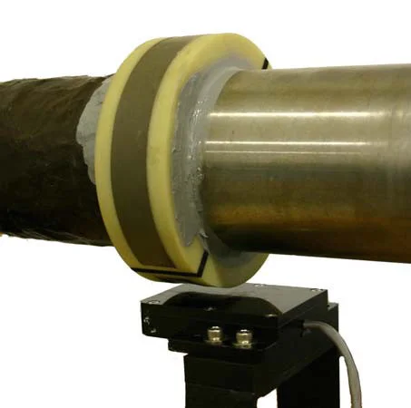
The bridge is wired to the supplied Deutsch connector. The CIT is laid on mounting tape and strapped to the shaft with cable ties tightened by a tensioning tool, or with stainless steel hose clamps; a counterweight sits 180° opposite on fast shafts. The primary hoop passes around the shaft, centred over the CIT with an air gap of about 12.7 mm (0.5 in), and the PICT housing is bolted to a fixed surface. At power-up a 3 s shunt calibration sequence runs. The system takes 9 to 36 V DC, 2 A.
It measures half-shaft torque on vehicles, for long tests where induction power replaces batteries; its datasheet shows it on a gaged automotive half shaft, inside its primary coil.
Specifications
| Channels | 1 · 2 |
|---|---|
| Input | Strain gage bridge (full bridge) |
| Output | Analog voltage |
| Output range | −10 to 10 V |
| Sample rate | 7 kHz (M540; 3 kHz with M320) |
| Resolution | 14 bit (M540; 12 bit with M320) |
| Latency | ≤ 0.3 ms (unfiltered, M540; 0.67 ms with M320) |
| Bridge input range | 0.1 to 10 mV/V |
| Gain setting | Software · Fixed (USB programmer (M320); fixed (M540)) |
| Shunt resistor | 100 kΩ (standard; other values available) |
| RF band | 2.4 GHz |
| RF channels | 16 |
| Transmission distance | 3 to 4 m (M540; 1 to 2 m with M320) |
| Supply voltage | 9 to 36 V |
| Power source | Induction |
| Bridge resistance | 350 Ω (minimum) |
| Supply current | 2 A |
| Shaft diameter | 25 mm (minimum) |
| Dimensions | 53 × 53 × 27 mm (transmitter, 63 mm high with connector) |
| Operating temperature | −40 to 85 °C (CIT and PICT) |
| Protection | IP67 |
Request a quote
Resources
Datasheets and manuals
Drawings
None for this product.
CAD models
Related applications
-
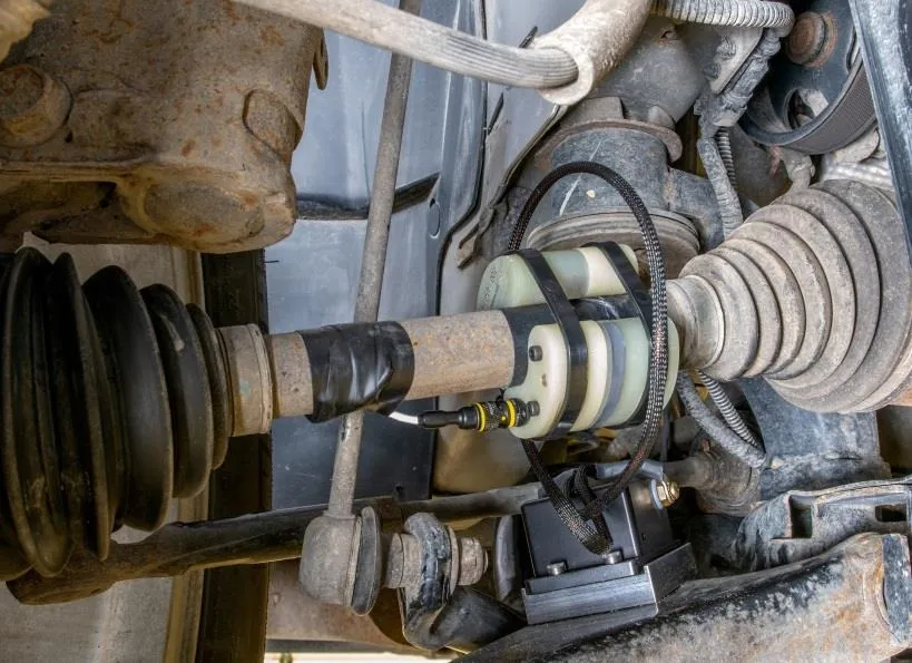 Powertrain Axle and half-shaft torque Drive torque measured on the production shaft, with a slip ring or telemetry to bring the signal out.
-
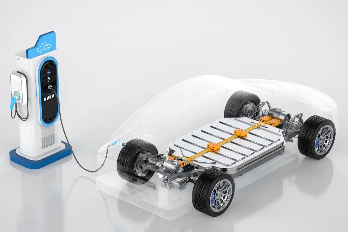 Electric EV powertrain torque Torque at each stage of the electric drivetrain, from gearbox shafts to the wheel, to see where power is lost.
-
 Efficiency Vehicle efficiency and power mapping Torque and speed measured at each driveline stage, from engine to wheel, so each power loss has a location.
-
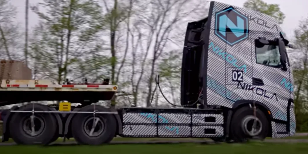 Powertrain Truck solid axle torque Drive torque on a truck solid axle, read by strain gages inside the shaft and brought out at the wheel.
In the same family
- Battery instead of induction CBT
Battery clamp-on transmitter for two strain gage bridges, up to 48 h.
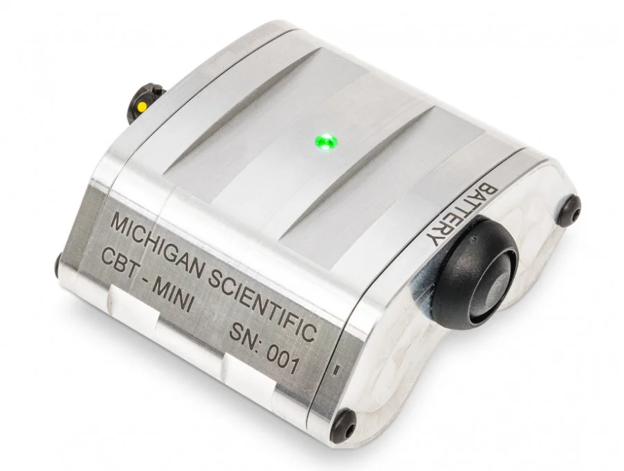
- Battery, smaller package CBT-mini
Small battery clamp-on transmitter for one strain gage bridge, up to 28 h.
- Split collar, more channels TEL-SC
Split collar with telemetry and induction power built in, for shafts from 23 mm.
A question on this product?
Describe the measurement. An application engineer answers.
More details to give? Use the full contact form.