Skip to content

Wheel force transducers

Six load components at the wheel center, while the vehicle is driven.

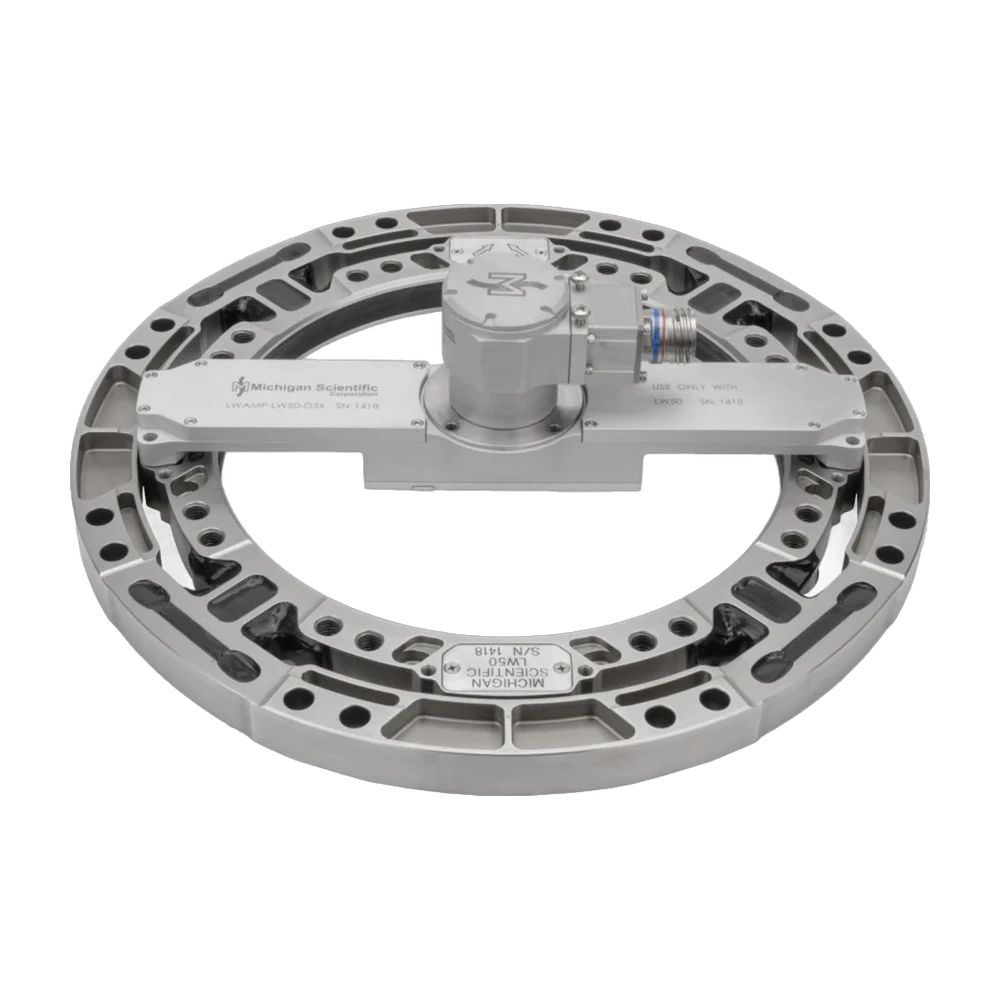
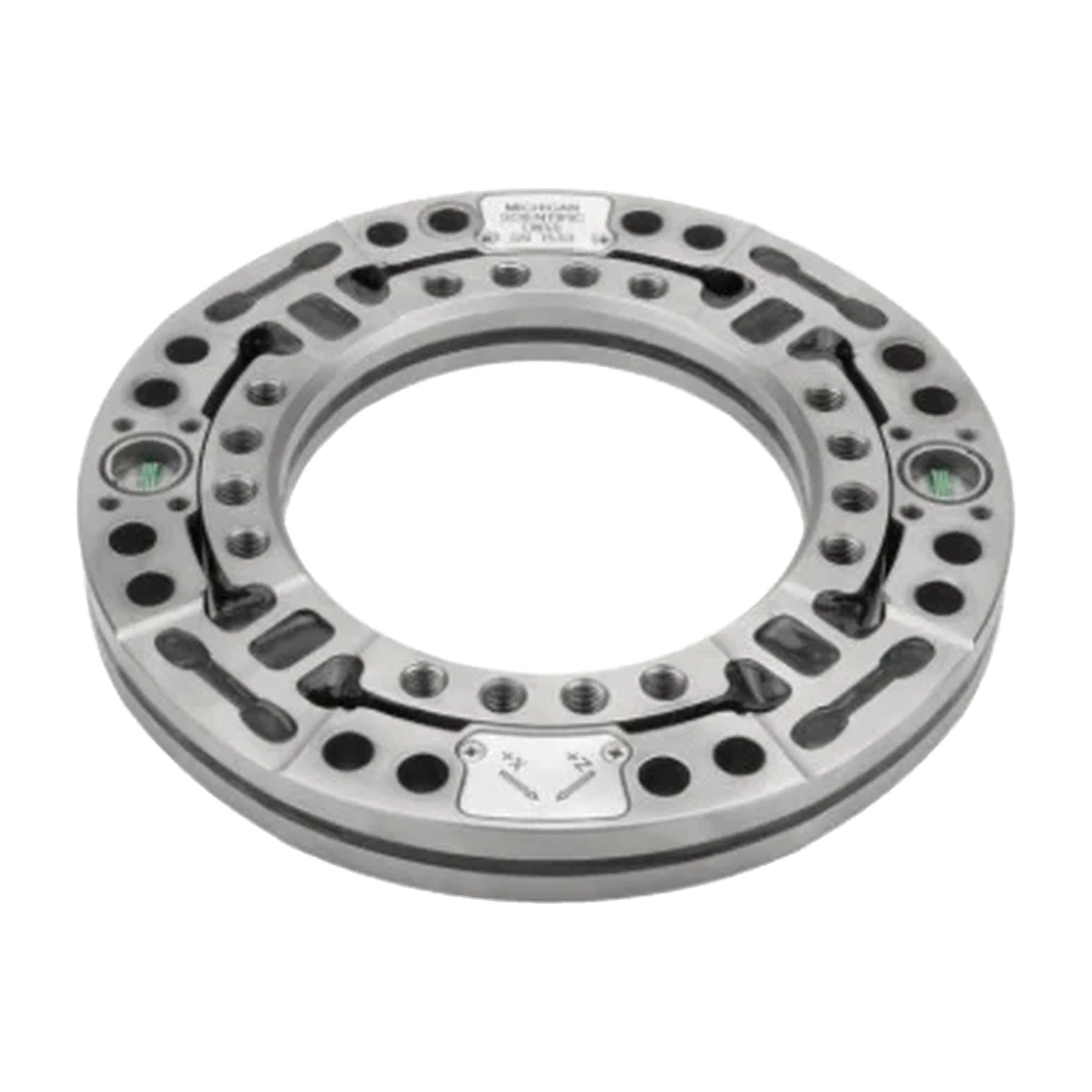
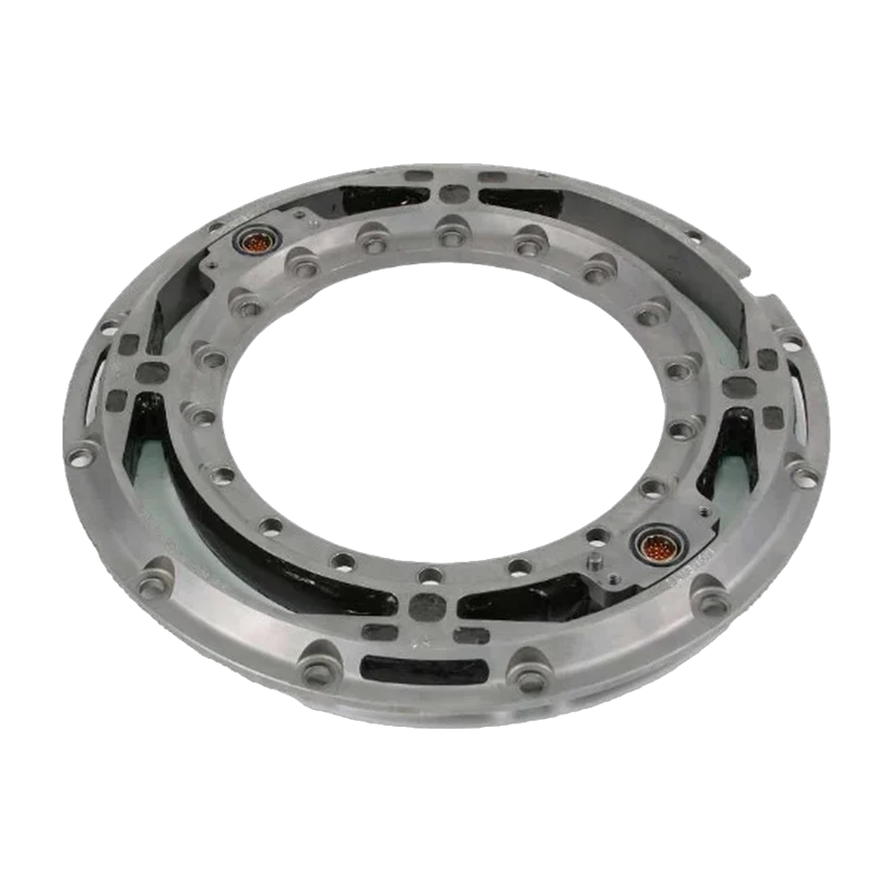
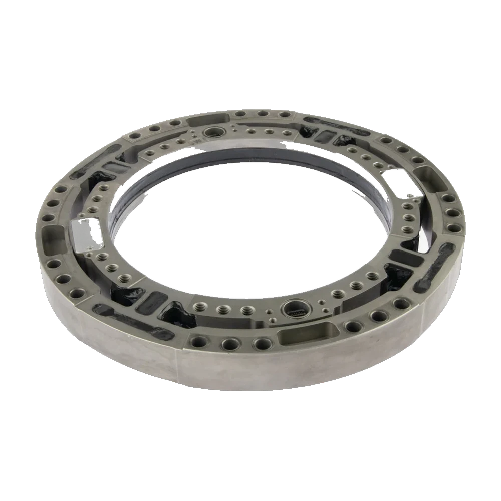
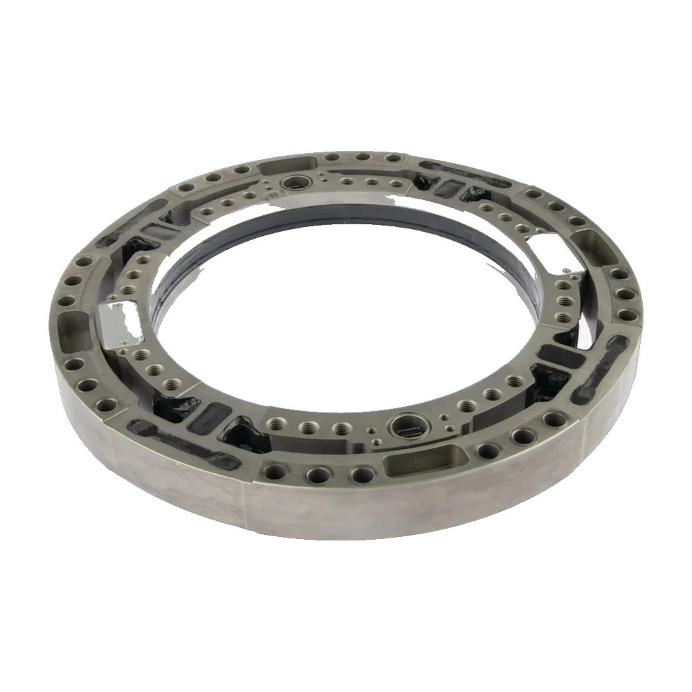
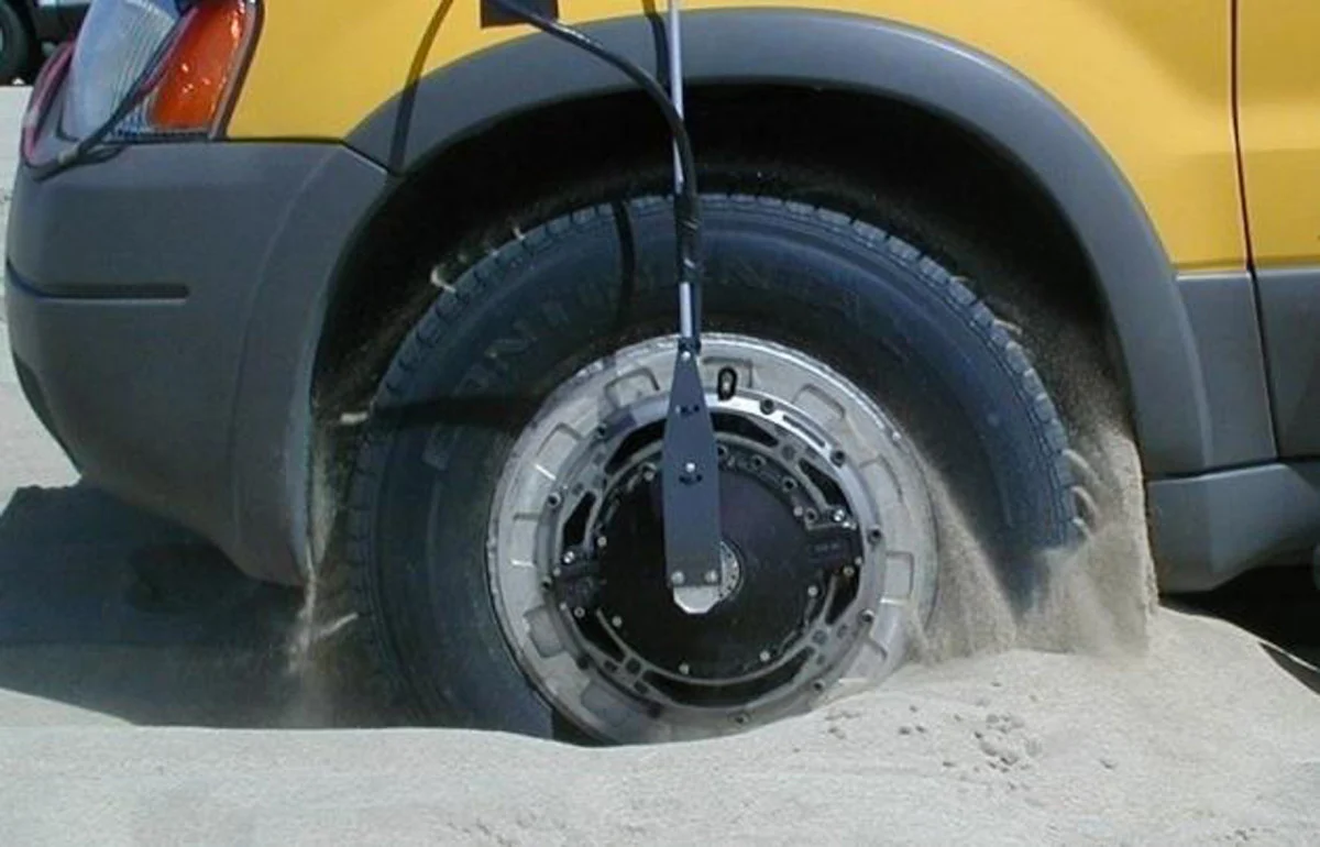
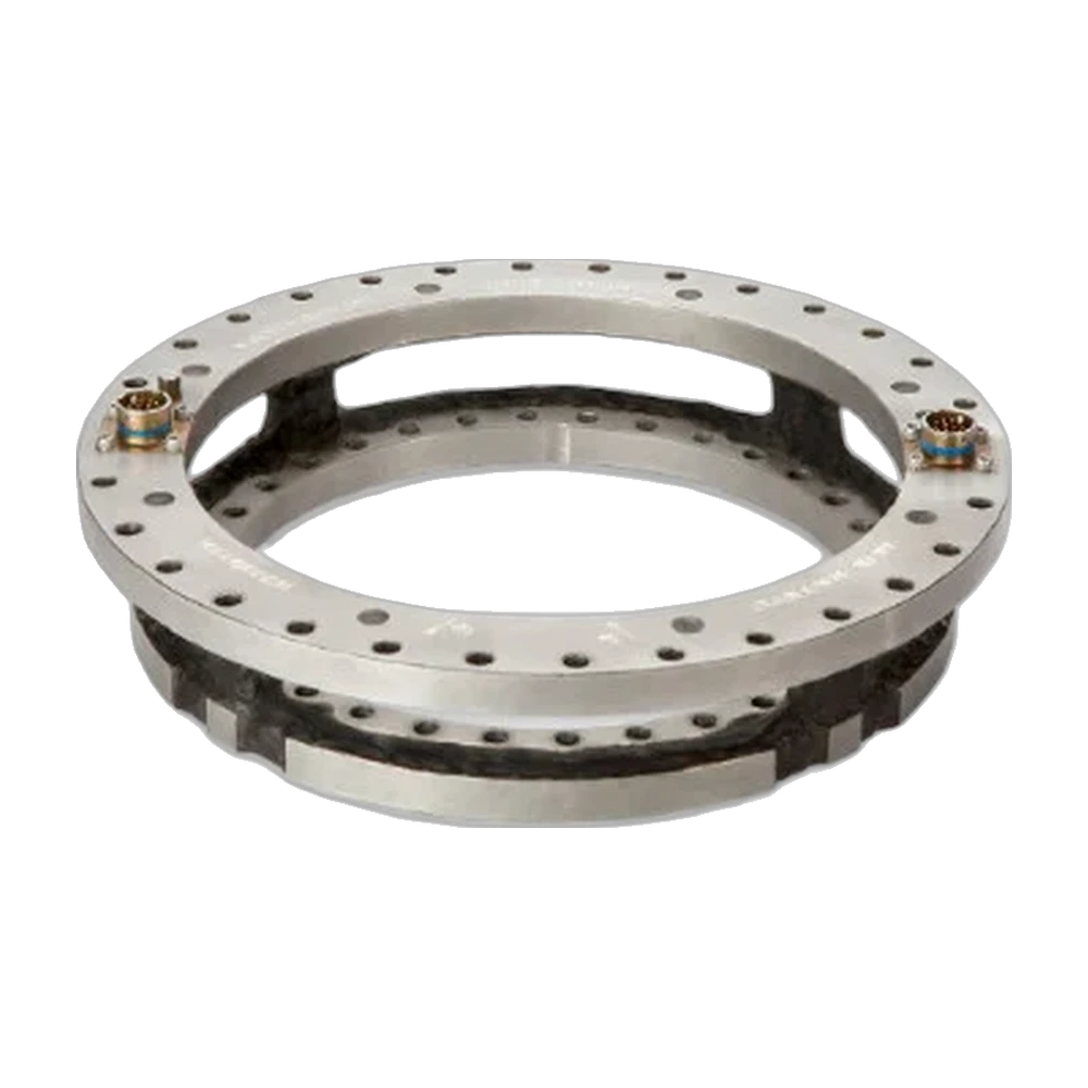
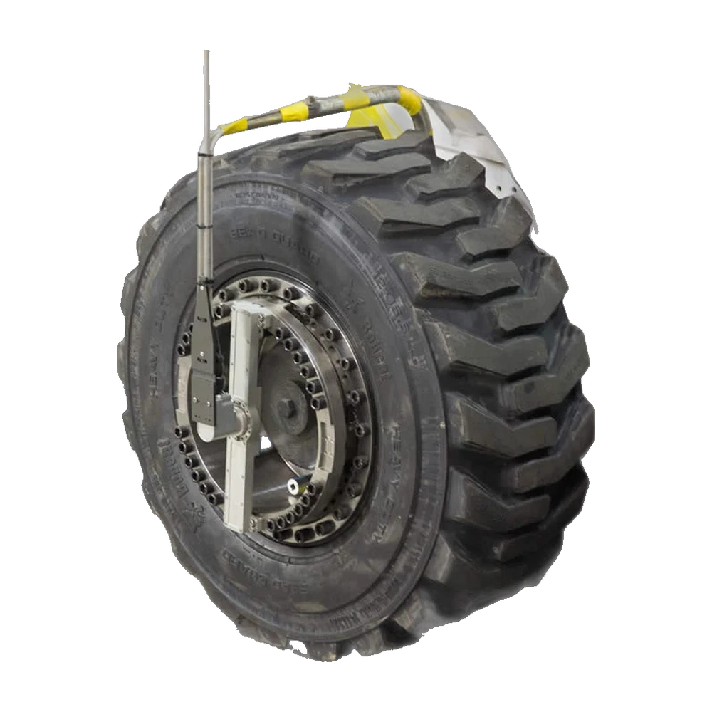
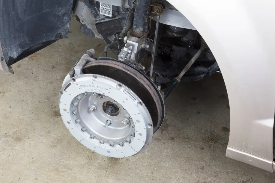
A wheel force transducer measures every load the road puts into the vehicle, at the wheel and while it is driven, to develop its durability, handling, ride and efficiency. Michigan Scientific has designed and built them for more than 25 years. The result is the widest range in the world, rugged enough for daily use in the field, precise on all six components and simple to fit on any vehicle.

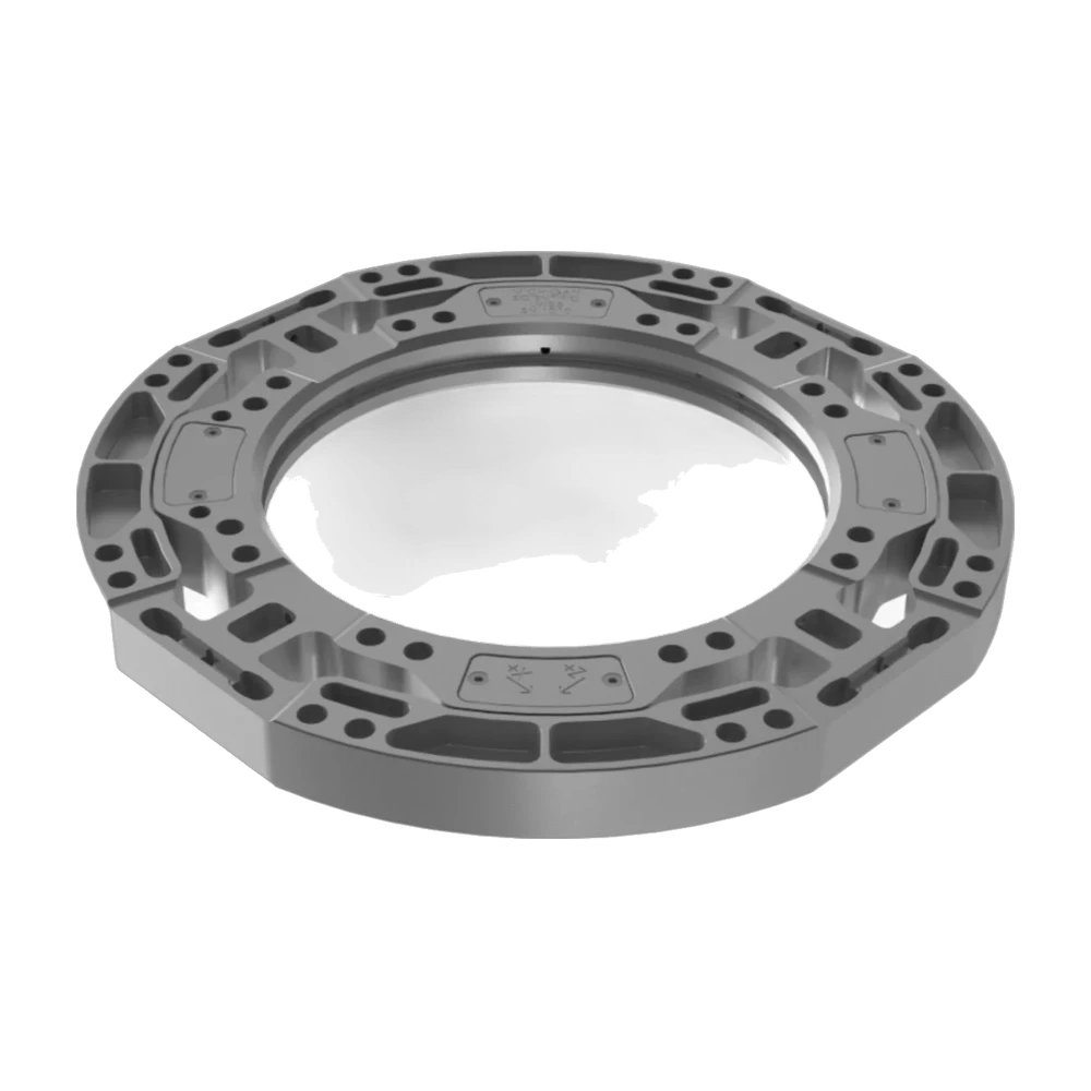
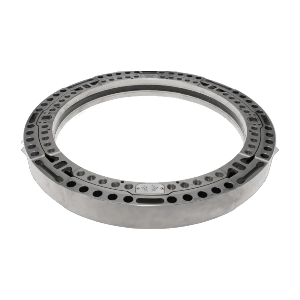
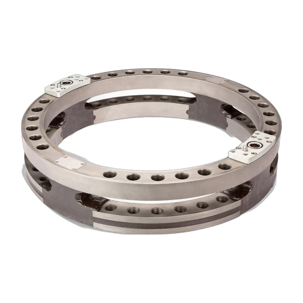
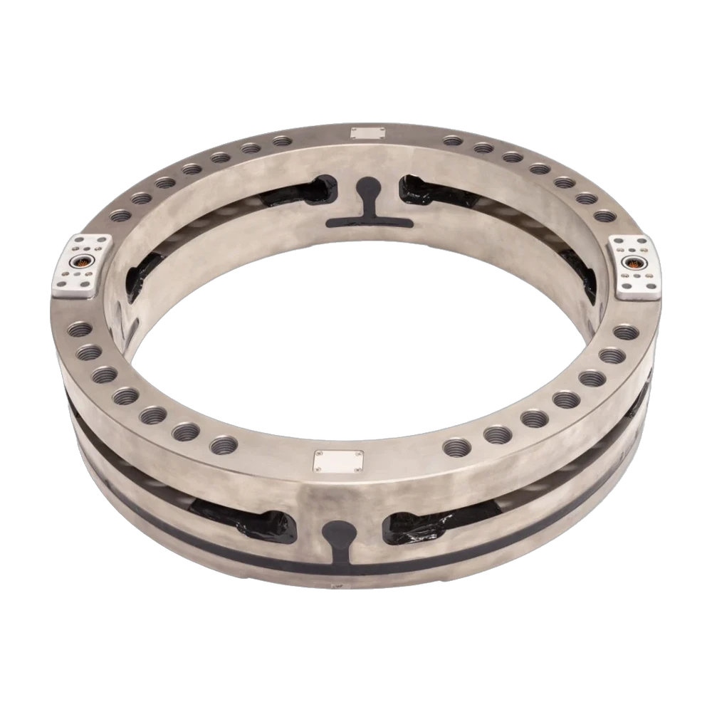
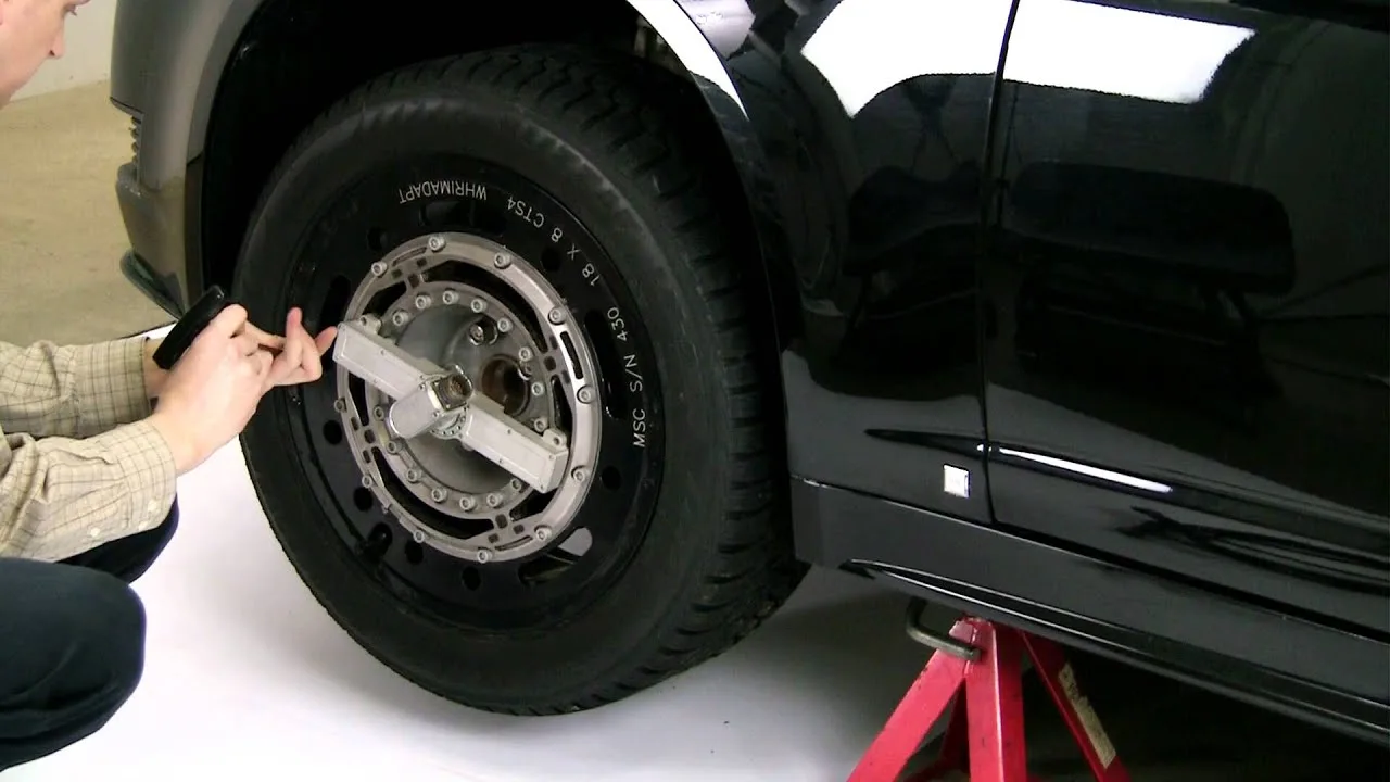
Wheel force transducer, cut out
3 forces · 3 moments
plus X and Z accelerations (X, Y, Z on the LW50 and LW55)
15.5 to 700 kN
force capacity, LW series
0.17°
wheel angle resolution, slip ring versions
ISO 17025
accredited calibration laboratories, Michigan Scientific

A simple, reliable and accurate setup for daily use in the field.

Two adapters made for your vehicle, a transducer, a telemetry transmitter or a slip ring, and one interface box. The transducer is weatherproof and temperature compensated, and each one is calibrated on all six components. To move the system to another vehicle, only the two adapters change.

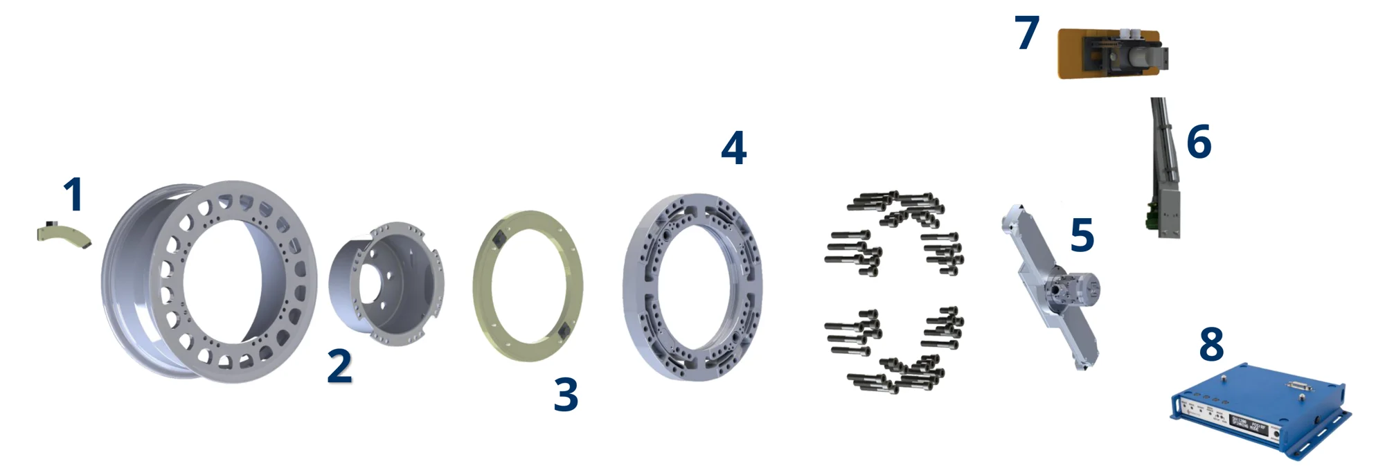
Exploded view of a wheel force transducer assembly: stator restraint, hub and rim adapters, telemetry transmitter, transducer, slip ring and amplifier, restraint rod, stator angle correction device and interface box
The complete assembly, with both transmission types. A given wheel uses the telemetry transmitter (3) or the slip ring (5).
  1. 2

    Hub and rim adapters made for your vehicle

    The only parts made for your vehicle. The hub adapter follows the bolt circle and wheel offset, the rim adapter follows the tire size.

  2. 4

    Wheel force transducer standard

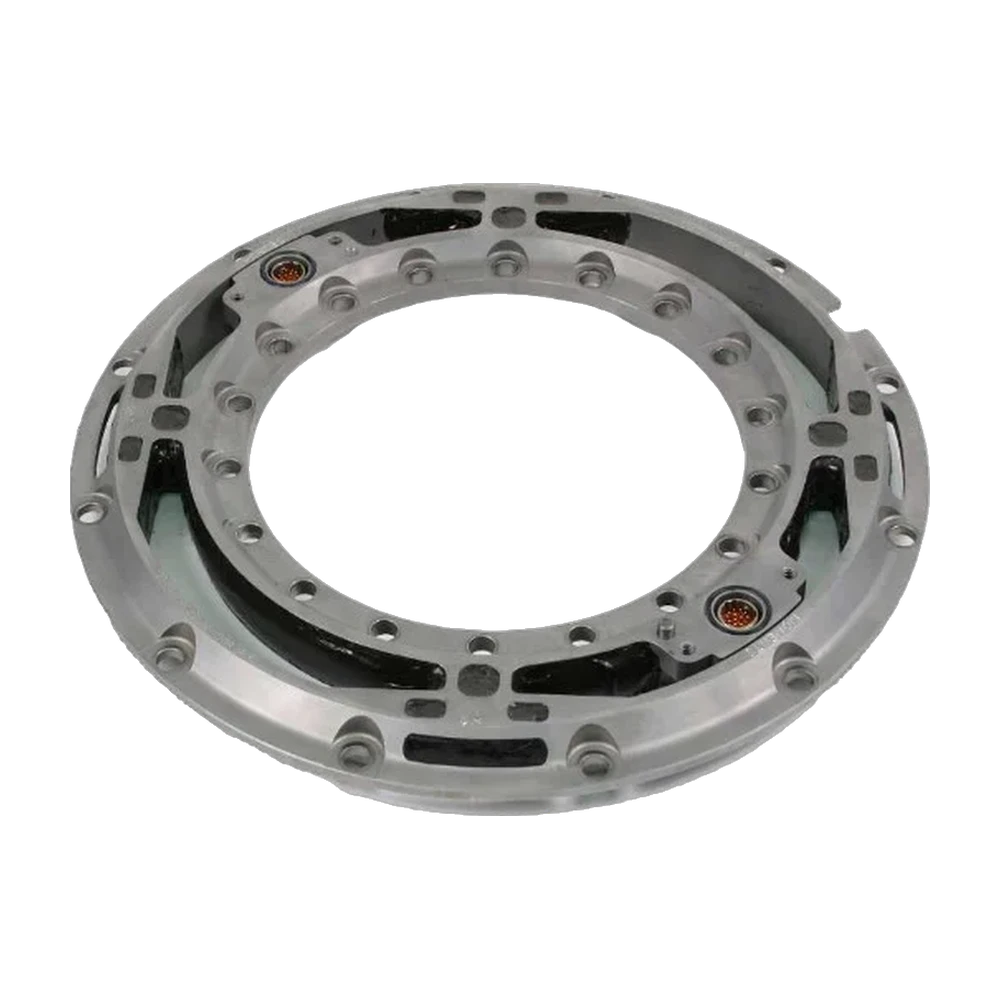
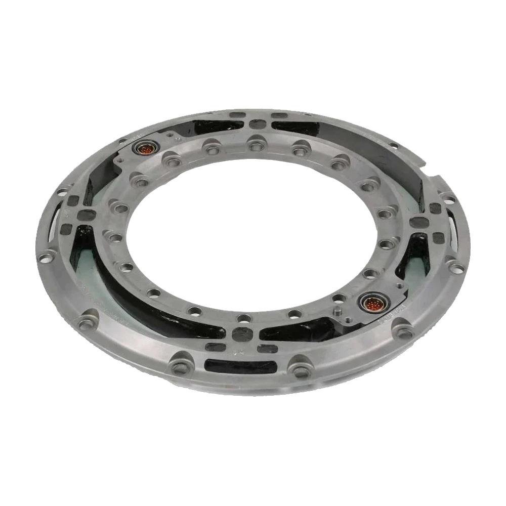
    Takes the place of the wheel center. Four-arm strain gage bridges, weatherproof, temperature compensated.

    3 forces · 3 moments · 2 accelerations

  3. 3 or 5

    Telemetry or slip ring standard

    An inboard telemetry transmitter, powered by induction, or an outboard slip ring with its spinning amplifier. Both digitize the signals on the wheel and fit the same transducer.

    also carries wheel speed and angle

  4. 1 · 6 · 7

    Stator restraint and angle correction standard

    A bracket for telemetry, a rod for the slip ring. On a steered wheel, the stator angle correction device (SAC) corrects the wheel angle in real time, so the loads are resolved into vehicle axes with the right angle and no custom over-the-wheel bracket is needed.

  5. 8

    CT3 interface box standard

    In the cabin. Resolves the loads into vehicle axes and corrects the crosstalk between components, in real time, with a front display, a USB-C connection to its embedded web page and IEEE 1588 PTPv2 synchronization.

    CAN 2.0 · CAN FD · analog · EtherCAT · Ethernet

2
vehicle-specific parts
2
transmission types, on the same transducer
1
interface box, for slip ring and telemetry

Wheel force transducer selection

Vehicle, static wheel load, peak Fx and Fz, peak My, rim size. Models meeting every criterion, ranked by margin.

Set the criteria. Closest models first.

Vehicle mass, rim size and test type available? Send them, an application engineer selects the transducer and the adapters. Send the data

Three forces, three moments, two accelerations.

All the loads between the road and the vehicle pass through the wheel center. The transducer measures them there, each as an independent signal, expressed in vehicle axes.

The six load components at the wheel center Side view of a wheel. Fx points forward, Fz upward, Fy toward the viewer. Mx turns about the forward axis, My about the axle, Mz about the vertical axis. Fx Fz Fy My Mx Mz
FxLongitudinal force
Braking and traction. ABS and traction control events, rolling resistance.
FyLateral force
Cornering. Lane change, handling and tire characterisation.
FzVertical force
Wheel load and its transfer. Potholes, kerbs and durability load spectra.
MxOverturning moment
About the longitudinal axis. Camber effects and wheel bearing loads.
MyDrive and brake torque
About the axle. Driveline and brake torque at each wheel.
MzAligning moment
About the vertical axis. Steering efforts and tire aligning torque.
ax · az
X and Z acceleration at the wheel (X, Y, Z on the LW50 and LW55)
n
wheel speed
θ
wheel angle, resolution 0.17° with slip ring

From a motorcycle to a harvester, on-road and off-road.

The LW series covers radial capacities from 15.5 to 700 kN, in five vehicle classes. It is the widest wheel force transducer range in the world.

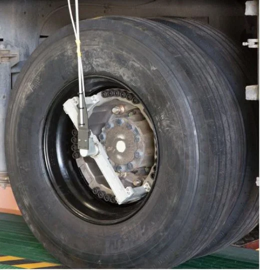
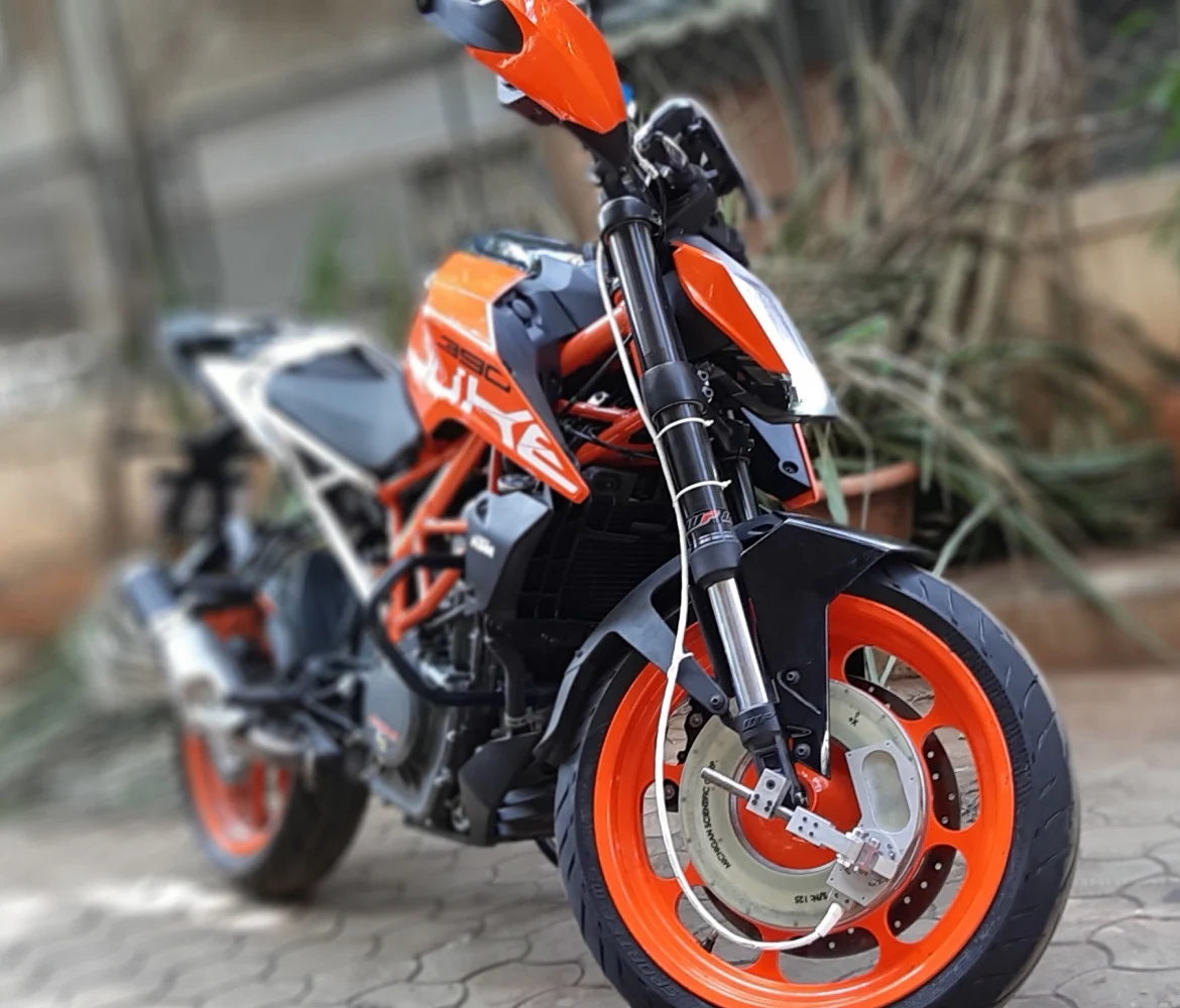
  1. LW-MC-3.5K wheel force transducer on a motorcycle wheel

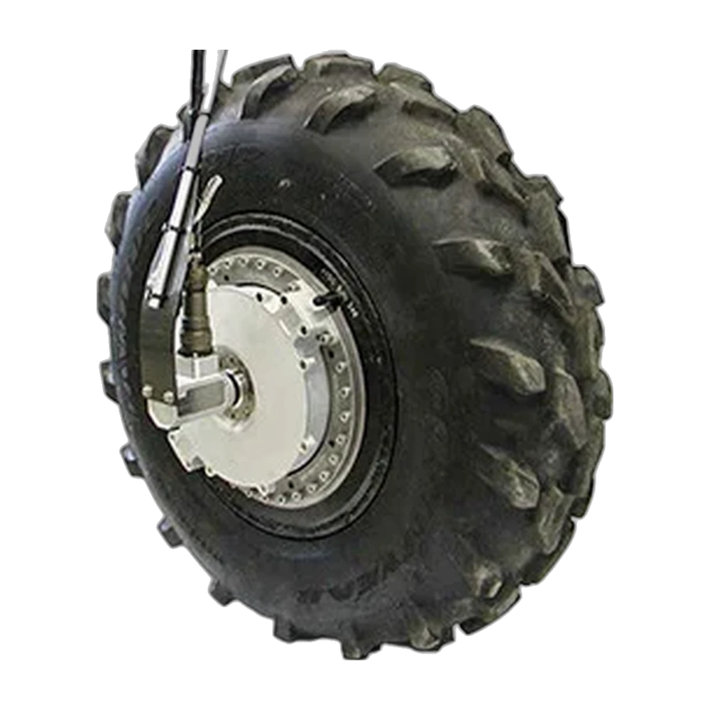
    Motorcycles, ATVs and small vehicles

    15.5 to 55 kN LW-MC-3.5K · LW25 · LW9.5 · LW55
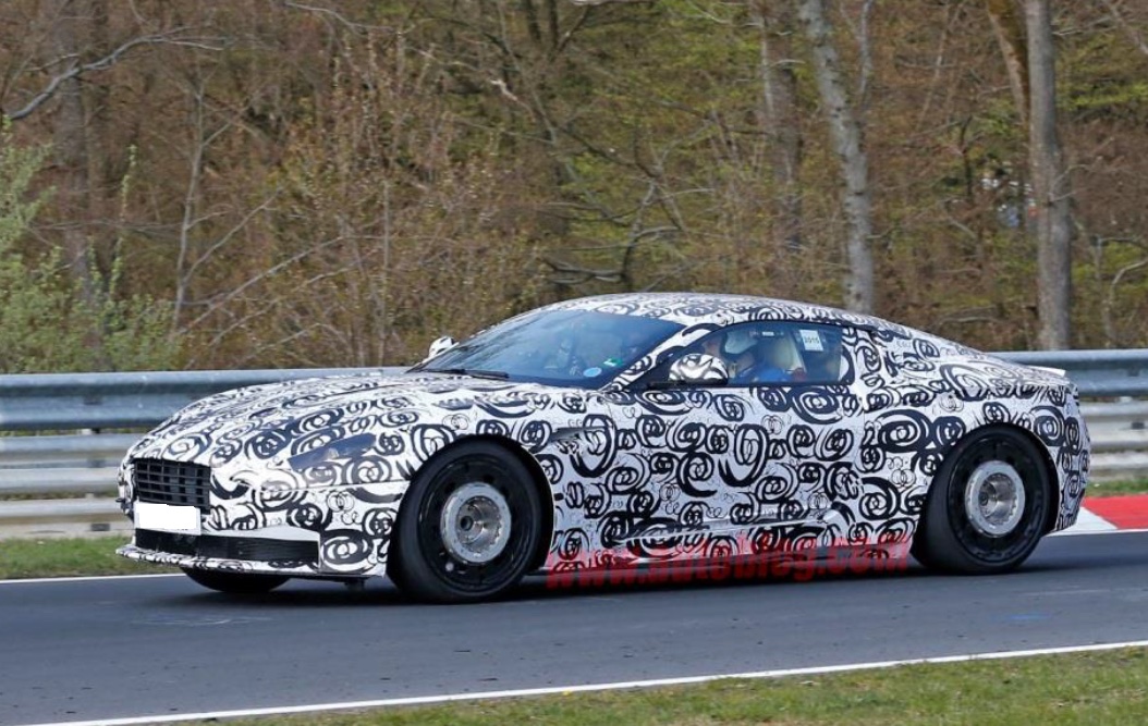
  2. Camouflaged sports car on a track with wheel force transducers on its wheels

    Passenger cars and racing

    50 to 65 kN LW12.8-50 · LW12.8-50-TEL · LW50 · LW12.8-60 · LW60 · LW65
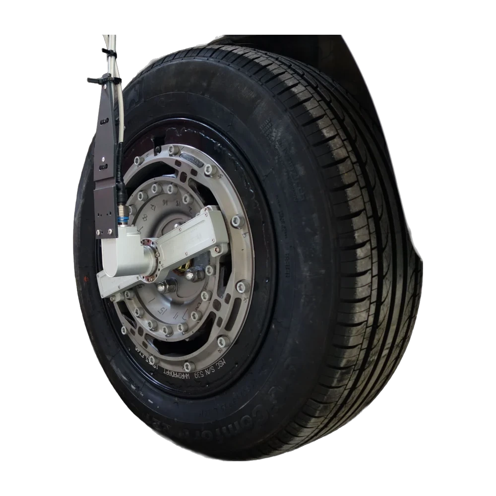
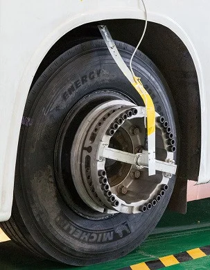
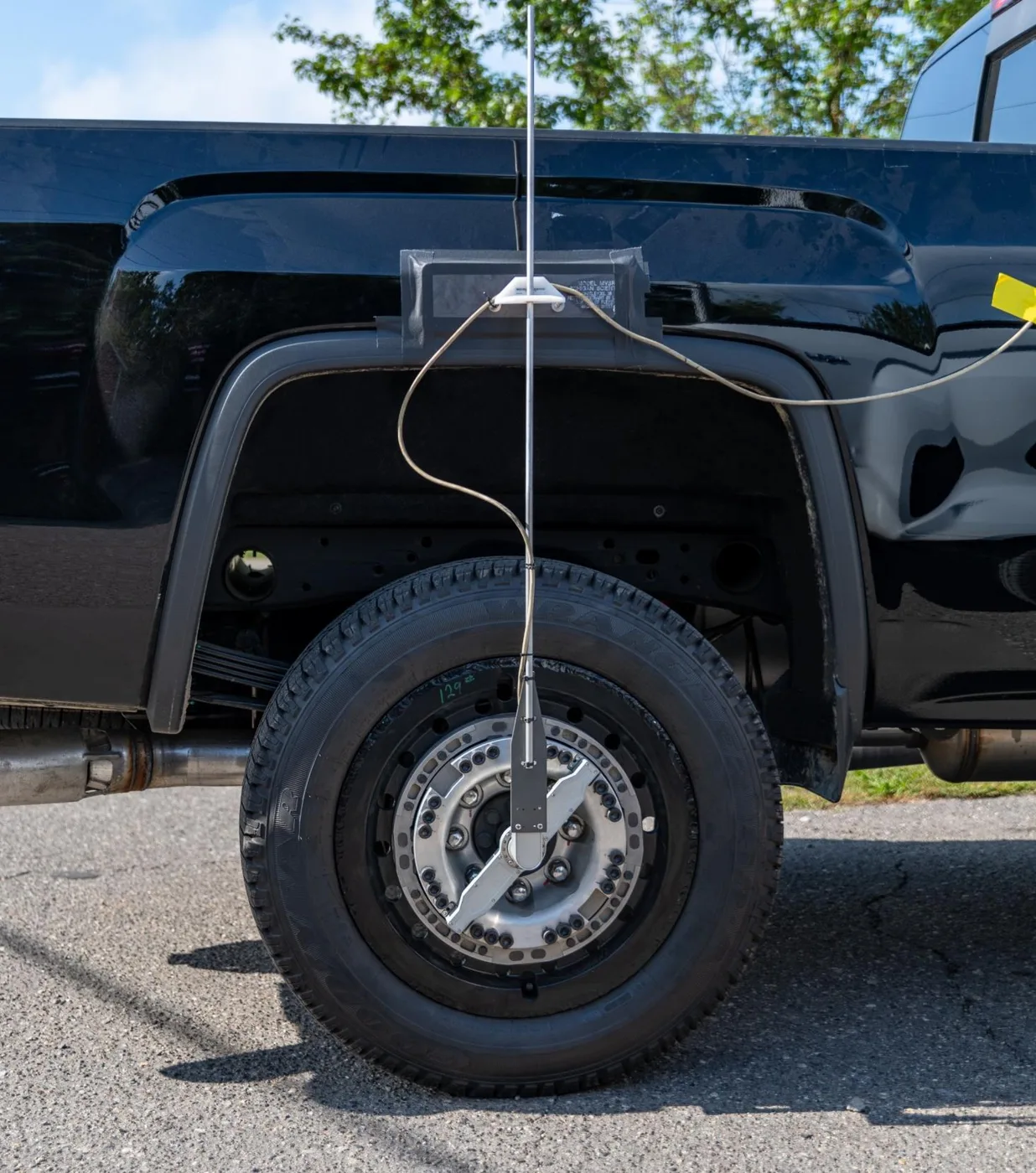
  3. Pickup truck rear wheel with a slip ring wheel force transducer

    Commercial vehicles, light trucks and forklifts

    55 to 178 kN LW55 · LW-2T-20K · LW9.5-HS · LW-2T-30K · LW150 · LW-2T-40K
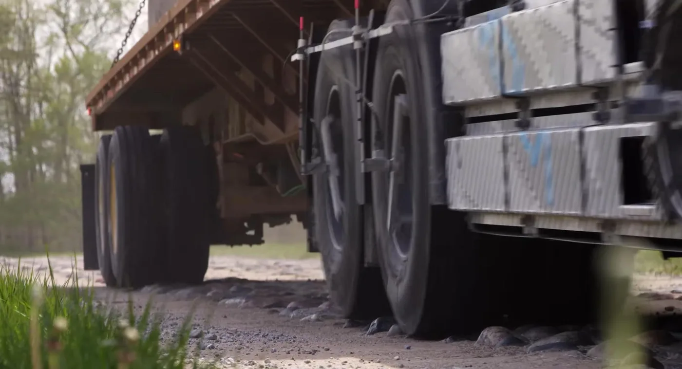
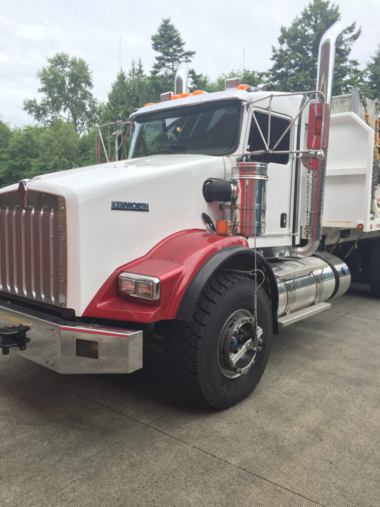
  4. Heavy truck with wheel force transducers on a gravel road

    Buses and heavy trucks

    222 to 445 kN LW-2T-50K · LW-2T-60K-S · LW-2T-100K-S
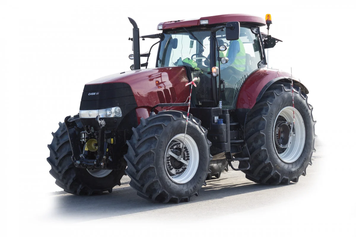
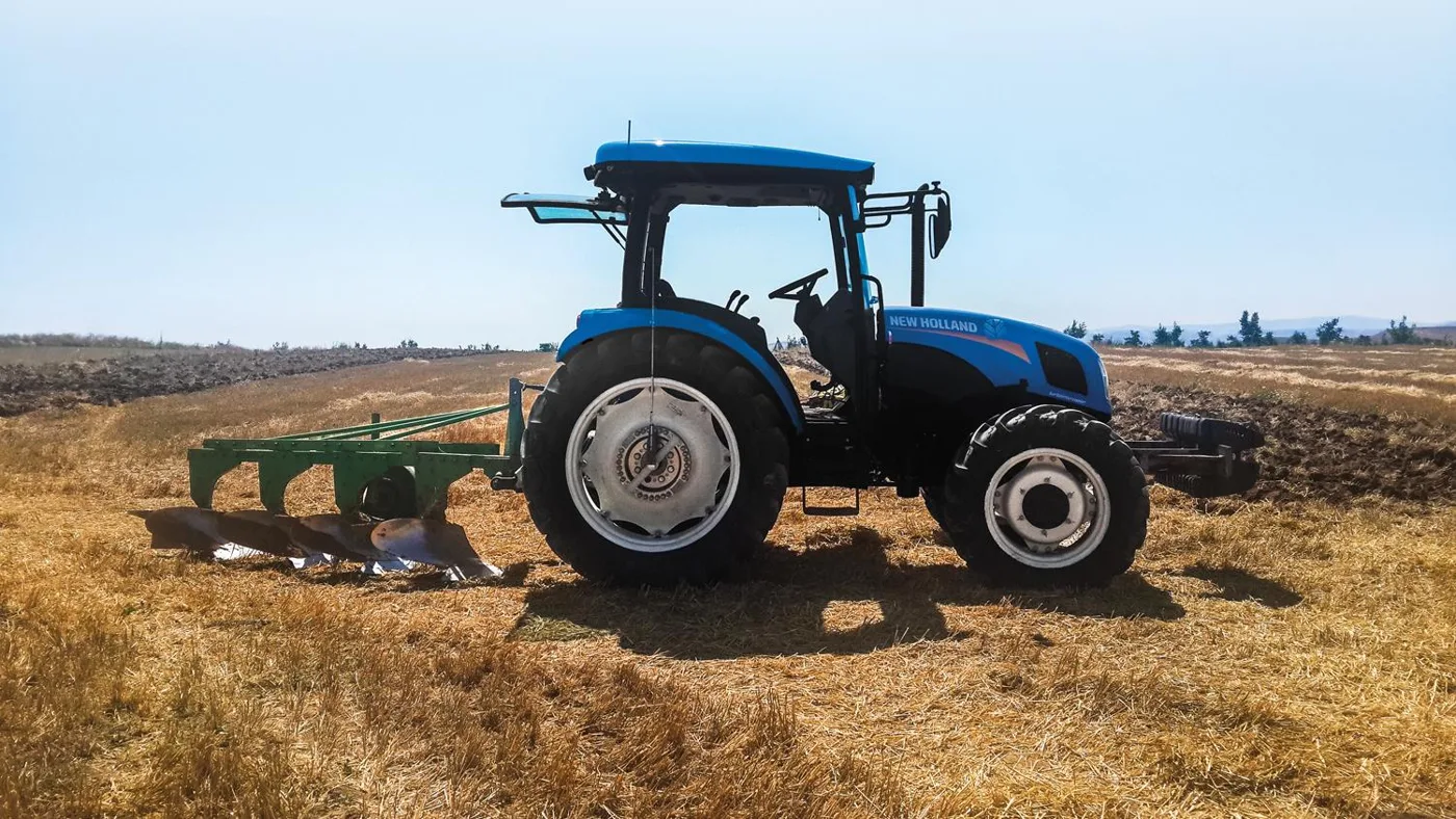
  5. Tractor ploughing a field with wheel force transducers on both axles

    Mining, defence and agriculture

    300 to 700 kN LW-2T-60K-S · LW-2T-100K-S · LW-2T-100K · LW700

Capacities are the radial force Fx, Fz of the models listed. Wheel force transducers supplied since 1999 to vehicle manufacturers, tire makers, test laboratories and defence.

Test teams that measure with Michigan Scientific

  • Michelin
  • Stellantis
  • BorgWarner
  • Bosch
  • Mahle
  • Audi
  • Tesla
  • CNH
  • AGCO
  • Rivian
  • Irizar
  • Volvo
  • IDIADA
  • UTAC
  • Ford
  • GM
  • Honda
  • Hyundai

Easy to install and use.

The assembly takes the place of the wheel on the hub, with no modification to the vehicle. The interface box is set up from its embedded web page, with no software to install. Fitting four wheels takes less than one hour.

  1. 01

    Mount

    Bolt the assembly to the hub, in place of the wheel.

  2. 02

    Restrain

    Fix the stator restraint. With the angle correction device, no custom over-the-wheel bracket is needed.

  3. 03

    Set up

    Connect to the embedded web page of the interface box. The front display of the CT3 shows the settings, the serial number of the connected transducer and any error code.

  4. 04

    Record

    The loads arrive in vehicle axes on CAN, CAN FD, analog, EtherCAT or Ethernet.

Free remote training session with each rental. On-site support and road load data acquisition service are available.

8:51 · Installation and setup of the LW65 telemetry wheel force transducer. The video is loaded from YouTube when you press play.

What a recording shows.

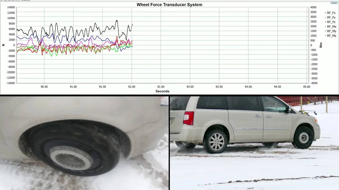
Three recordings made with LW transducers. The annotations are those of Michigan Scientific.

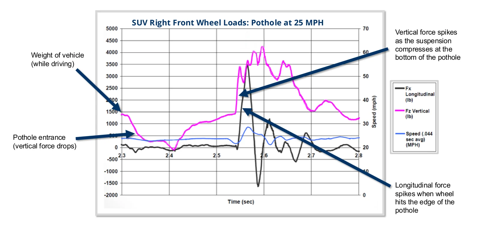
  • Annotated chart: longitudinal force, vertical force and speed of an SUV right front wheel over a pothole at 25 mph

    Pothole at 40 km/h (25 mph)

    Right front wheel of an SUV. The vertical force drops at the pothole entrance, then spikes as the suspension compresses at the bottom. The longitudinal force spikes when the wheel hits the edge.

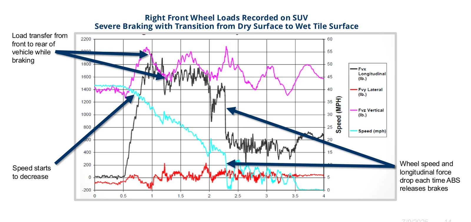
  • Annotated chart: longitudinal, lateral and vertical force and speed during severe braking with a transition from dry surface to wet tile

    ABS braking, dry to wet surface

    Right front wheel of an SUV. The load transfers from rear to front during braking. Wheel speed and longitudinal force drop each time the ABS releases the brakes.

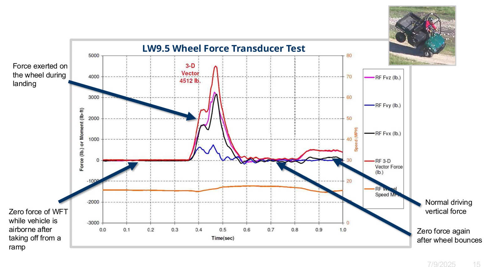
  • Annotated chart: forces at the right front wheel of a utility vehicle taking off from a ramp and landing

    Landing after a ramp

    LW9.5 on a utility vehicle. The force is zero while the wheel is airborne, peaks at landing, and returns to zero when the wheel bounces.

Original charts in lb and mph.

Rent for a campaign. Buy when the need stays.

The same transducers, calibration and support either way. A rental can turn into a purchase.

Long term

Purchase

Best forFor recurring tests, a dedicated rig, or a model made to your vehicle.

Advantages

  • Any model of the range, standard, configured or custom.
  • Lowest cost per test over time.

Limits

  • Capital expenditure and delivery lead time.

Custom transducers for unusual bolt patterns, motorsport hubs, agricultural and off-highway wheels are made to order.

Resources

CAD files, brochures and guides to choose, design and set up a wheel force transducer.

Frequent questions

Force transducer or torque transducer?

Choose an LW wheel force transducer when you need the loads the road puts into the vehicle: durability, vehicle dynamics, road load data for a rig. Choose a TW wheel torque transducer, a separate family, when you only need drive and brake torque: driveline efficiency, drag torque, rolling resistance.

Does it fit my wheel?

The transducer mounts between a rim adapter and a hub adapter designed from the profile of your original rim. Minimum rim size depends on the model, from 8 in for an LW25 with a two-piece rim adapter.

Slip ring or telemetry?

Both carry the same signals and are swappable on the same transducer. The slip ring assembly is wired and contains the encoder. The telemetry transmitter is powered by induction and sends the digitized signals by radio to the telemetry stator, which holds the encoder pick-ups.

Can it be used on a test rig?

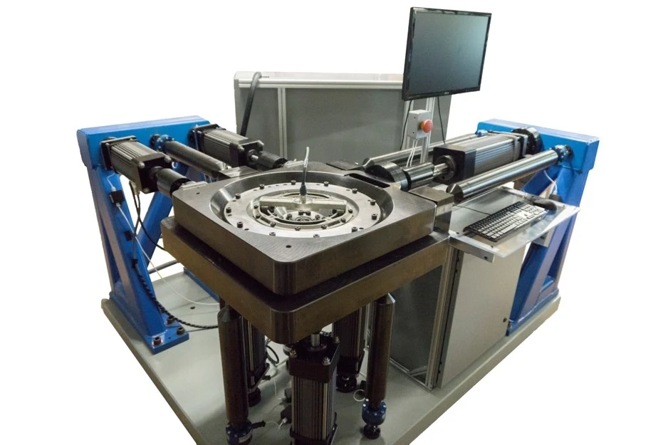
Yes. An LW transducer mounts on a rig through flanges or hubs, spinning or not.

Can I rent a set?

Yes. The rental fleet holds over 30 wheel force transducers, commercial vehicle models included, and many adapters. A rent-to-own program, a free remote training session, on-site support and a road load data acquisition service are available.

Which model for your vehicle?

Send the vehicle, the wheel size and the quantity. You get a configured offer, to buy or to rent.

More details to give? Use the full contact form.

Contact us

An application engineer replies within 24 hours on working days. Use the full contact form.