
Measuring drive torque on the production axle, while the vehicle is driven
In brief
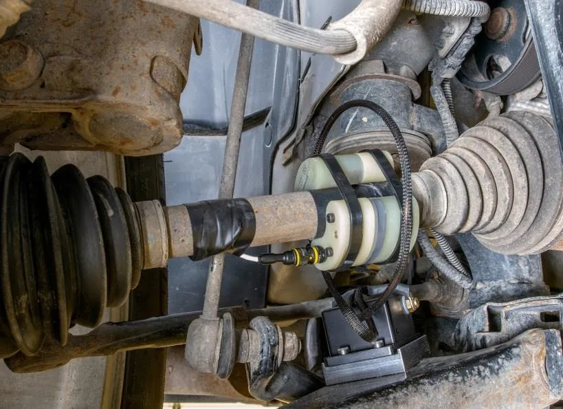
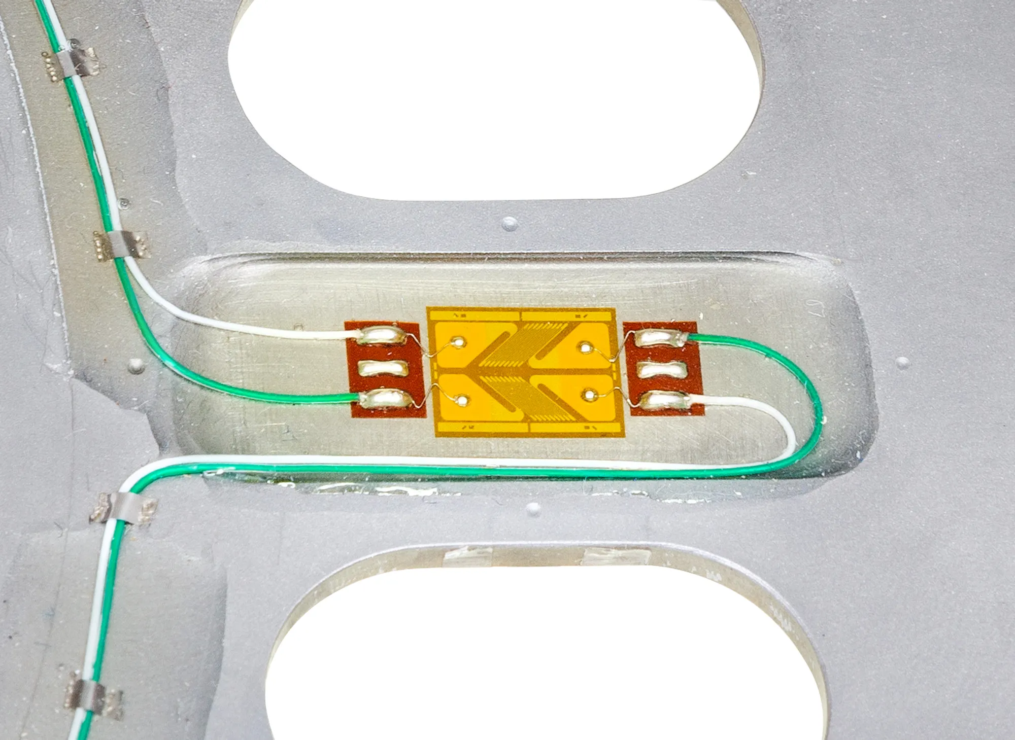
The production half-shaft is fitted with a strain gage bridge and calibrated in torque, so the shaft itself is the transducer. A tubular slip ring slides over the shaft, or a clamp-on transmitter is strapped to it, and carries the bridge signal to the recorder while the vehicle is driven. On a solid axle, where the housing leaves no room around the shaft, the gages go inside a bore drilled through it and the signal leaves at the wheel.
- 25 mm
- smallest shaft diameter for the CBT, CBT-mini and CIT
- 48 h
- battery life of the CBT with one bridge
- 30 to 81.3 mm
- bores of the B-Series tubular slip rings
The shaft as transducer
Drive axle torque is one of the on-vehicle measurements of design validation. It is measured on the half-shaft of a front-wheel or all-wheel drive vehicle, or on the solid axle of a truck, with the parts the vehicle is built with. The shaft is gaged, calibrated on a torque calibration machine and refitted.
Two constraints set the setup. The bridge signal starts on a rotating part and has to reach a recorder that does not; and a half-shaft moves through the whole suspension travel between two boots, which leaves a short length of plain shaft for the slip ring or the transmitter.
Signal off the shaft
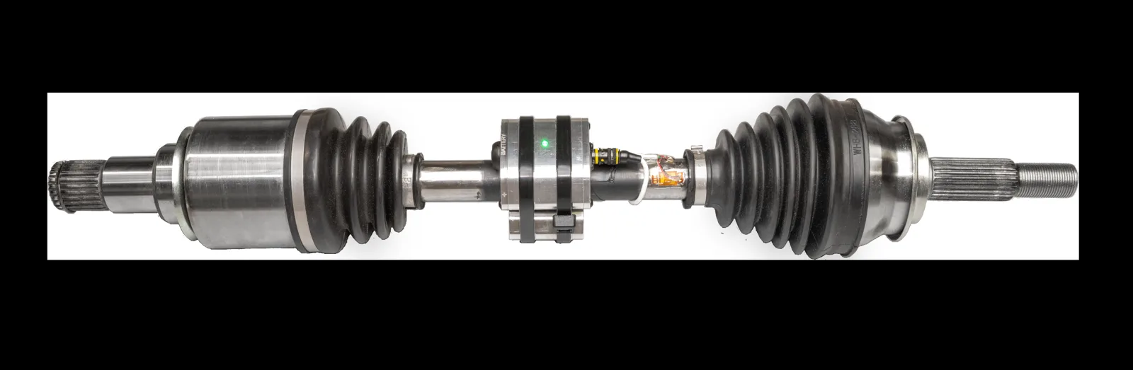
The choice is between a slip ring, which needs no power on the shaft, and telemetry, which has no contact. A battery transmitter needs the least room and suits short tests; an induction transmitter runs as long as the test does.
| B-Series tubular slip ring | slides over the shaft, 4 to 8 circuits, bores of 30 to 81.3 mm, 7 000 rpm on the 50.8 mm bore; weatherproof versions for water, mud, snow and dust; /E60 versions with a 60 ppr encoder |
|---|---|
| CBT | battery, two bridges, 48 h with one bridge, 36 h with two · 3 kHz, 12 bit, 2.4 GHz · shafts of 25 mm and more · IP67 |
| CBT-mini | battery, one bridge, 28 h · 7 kHz, 14 bit · 181 g with batteries · shafts of 25 mm and more |
| CIT | induction, one or two bridges, no battery · stationary primary coil around the shaft · shafts of 25 mm and more · IP67 |
| TEL-SC | split collar with built-in telemetry and induction power, fitted without dismantling the shaft ends · shafts of 23 mm and more · 1 to 3 channels under 76 mm, up to 12 above |
| Output | ± 10 V analog per channel at the receiver |
Solid axles
On a truck, the axle housing leaves no room for a slip ring or a transmitter around the shaft. A hole is drilled through the center of the axle shaft, past the hub bearings, and the gages are applied to its wall: deep-bore gaging goes up to 152 mm deep in a bore of 12.7 mm or more. The torque between differential and hub is read directly, with no effect from bearings or seals. The wires come out through the center of the hub to a sealed connector, and a slip ring or a telemetry package bolted to the standard wheel takes the signal from there.
Procedure
- 01
Gage and calibrate the shaft
A strain gage bridge on the production half-shaft or axle, calibrated in torque before it goes back on the vehicle.
Strain gaging and calibration - 02
Slip ring on the half-shaft
The B-Series rotor is secured to the shaft with set screws; the stator is held by a flexible restraint on the subframe.
B-Series tubular slip rings - 03
Or a clamp-on transmitter
The CBT, CBT-mini or CIT is laid on mounting tape and strapped with cable ties or hose clamps, with a counterweight 180° opposite on fast shafts. A 3 s shunt calibration runs at power-up.
Wireless telemetry systems - 04
Record torque with wheel speed
The /E60 slip rings add a 60 ppr encoder; at the wheel, the Wheel Instrumentation System takes an encoder up to 1 024 ppr.
Result
The drive torque at each wheel, measured on the part the vehicle is built with, on the road or the track. The signal path is chosen for the shaft and the test duration: slip ring, battery telemetry for short tests, induction telemetry for long ones.
Frequent questions
Can a telemetry transmitter be fitted without taking the half-shaft apart?
Yes. The CBT, CBT-mini and CIT strap to the gaged shaft, and the TEL-SC collar closes around it. None of them needs the shaft ends dismantled.
Slip ring or telemetry: which one for half-shaft torque?
A tubular slip ring needs no power on the shaft and its weatherproof versions take water, mud, snow and dust. A battery transmitter needs the least room and suits short tests, 48 h for the CBT with one bridge; an induction transmitter suits long ones.
How is torque measured on a truck solid axle inside its housing?
From the inside of the shaft. A hole is drilled through the center of the axle shaft, past the hub bearings, and the strain gages are applied to its wall. The wires come out through the center of the hub to a slip ring or a telemetry package on the wheel.
What is the smallest shaft that takes clamp-on telemetry?
25 mm for the CBT, CBT-mini and CIT; 23 mm for the TEL-SC split collar.
Similar applications
All applications-
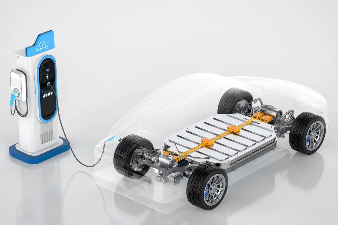 Electric EV powertrain torque Torque at each stage of the electric drivetrain, from gearbox shafts to the wheel, to see where power is lost.
-
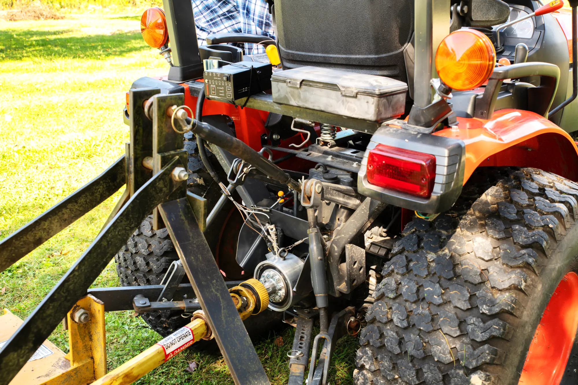 Agriculture PTO torque and power The torque and speed that the tractor delivers to the implement, measured during real field work.
-
 Engine Crankshaft measurements Torque, bending and strain on the production crankshaft with the engine running, in the vehicle or on the dyno.