
Measuring temperature on rotating parts with thermocouples and an end-of-shaft slip ring

In brief
Thermocouples are fixed to the rotating part and wired to a slip ring mounted on the end of the shaft. The rotor of the slip ring takes the sensor wires, the stator goes to the recorder. An amplifier on the rotating side turns the millivolt signal into 10 mV/°C before it crosses the contacts. The test runs on an engine dynamometer or on the vehicle: crankshaft bearings under load, an air conditioning compressor in operation, brake rotors during the stop.
- 4 to 36
- circuits on S-Series and SR Series end-of-shaft slip rings
- 12 000 rpm
- standard speed rating of the S-Series
- 10 mV/°C
- output of the AMP-TC-M1 and AMP-TCN-X2 amplifiers on the rotor
Signal path
A thermocouple on a rotating part turns with it, and its wires cannot go straight to a recorder. A slip ring assembly makes the link: its rotor turns with the shaft and carries the sensor wires, brushes fixed in the stator ride on its rings, and the stator hands the signals to the data acquisition system. The sensor wires run on the surface of the shaft or inside it, through a groove milled across the shaft end or an adapter.
An unamplified thermocouple signal is in the millivolt range, and the rings and brushes are not thermocouple alloys: a temperature gradient across the contacts adds an error. An amplifier on the rotating side, between the thermocouples and the slip ring, holds the cold junction compensation and sends a high-level voltage through the contacts, which the gradient and interference cannot affect.
Instrumentation
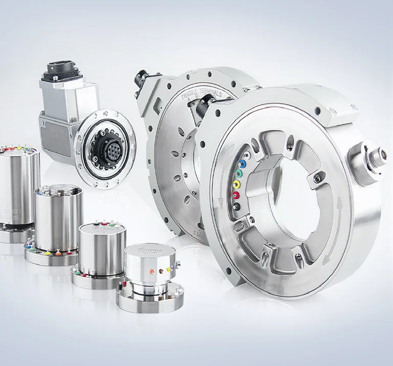
| Slip ring, 4 to 10 circuits | S-Series end of shaft, two screws, 12 000 rpm standard, 20 000 rpm in option, 500 mA per circuit, −40 to 121 °C |
|---|---|
| Where axial space is limited | Short S-Series, 4 to 10 circuits, from 22.15 mm long, 12 000 rpm; some models carry the thermocouple amplifiers in the rotor |
| Slip ring, 10 to 36 circuits | SR Series, 500 mA per circuit, 250 mA on the SR36; 12 000 rpm on the SR10M, 4 000 rpm on the SR20M, 2 400 rpm on the SR36M; weatherproof versions W or B |
| Amplifier on the part | AMP-TC-M1, 1 to 3 thermocouples of type E, J, K or T, 10 mV/°C, ± 10 V, adhered, potted or strapped |
| Amplifier on the rotor | AMP-TCN-X2, 1 to 9 channels per module, cold junction compensated, 10 mV/°C, pilots on the rotor of an SR series slip ring |
| Contacts | precious metal rings and brushes, 0.1 Ω peak noise; color-coded solder terminals; bearings lubricated for life |
Procedure
- 01
Fix the thermocouples to the part
At the points to monitor, near a bearing, on the compressor or on the brake rotor.
- 02
Route the wires to the slip ring
On the surface of the shaft or through its bore, to the rotor terminals of the slip ring mounted on the shaft end.
S-Series end-of-shaft slip rings - 03
Amplify on the rotating side
An AMP-TC-M1 fixed to the part, or an AMP-TCN-X2 on the rotor of an SR series slip ring, between the thermocouples and the rings.
AMP-TC-M1 thermocouple amplifier - 04
Record from the stator
The stator is connected to the data acquisition system. The signal is transferred while the part rotates under load.
Crankshaft, compressor, brakes
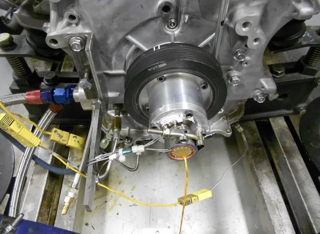
On an engine dynamometer, the slip ring is mounted on the crankshaft nose and the thermocouple wires are routed from the crankshaft bearings to it. The measurement shows whether the bearings overheat under high engine load.
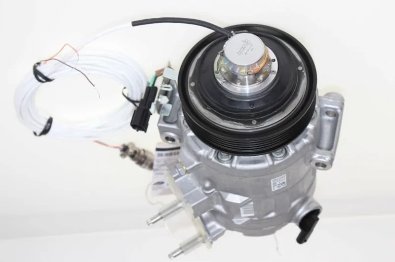
On an air conditioning compressor, the thermocouples are routed to an end-of-shaft slip ring on the compressor pulley. The compressor is driven by the engine, so the measurement is made with the engine running, on the dynamometer or in normal driving.
For brakes, the thermocouples are attached to the rotor or the hub and routed to a slip ring mounted outboard on the vehicle wheel, where the connections stay easy to reach.
Result
The temperature of the rotating part itself, recorded while it works: a bearing under engine load, a compressor in operation, a rotor during the stop. The same slip ring and amplifier serve on the dynamometer and on the vehicle; the SR Series exists in weatherproof versions for the road.
Frequent questions
How do you connect a thermocouple on a rotating shaft to a recorder?
Through an end-of-shaft slip ring. The thermocouple wires go to its rotor terminals, and the stator connects to the data acquisition system.
Should a thermocouple signal be amplified before the slip ring?
An amplifier on the rotating side turns it into 10 mV/°C before it crosses the contacts, which removes the error from the temperature gradient across the slip ring and from interference.
How many thermocouples can be amplified on the rotating side?
One to three with an AMP-TC-M1 fixed to the part, one to nine per module with an AMP-TCN-X2 on the rotor of an SR series slip ring.
How is brake rotor temperature measured on the vehicle?
The thermocouples are attached to the rotor or the hub and routed to a slip ring mounted outboard on the vehicle wheel.
Similar applications
All applications-
 Electric Temperature in electric vehicles Temperatures on the rotating parts of an electric motor, brought out by a slip ring with amplifiers in its rotor.
-
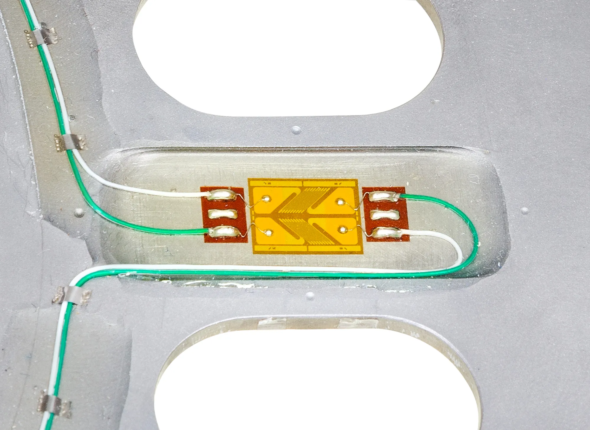 Engine Crankshaft measurements Torque, bending and strain on the production crankshaft with the engine running, in the vehicle or on the dyno.
-
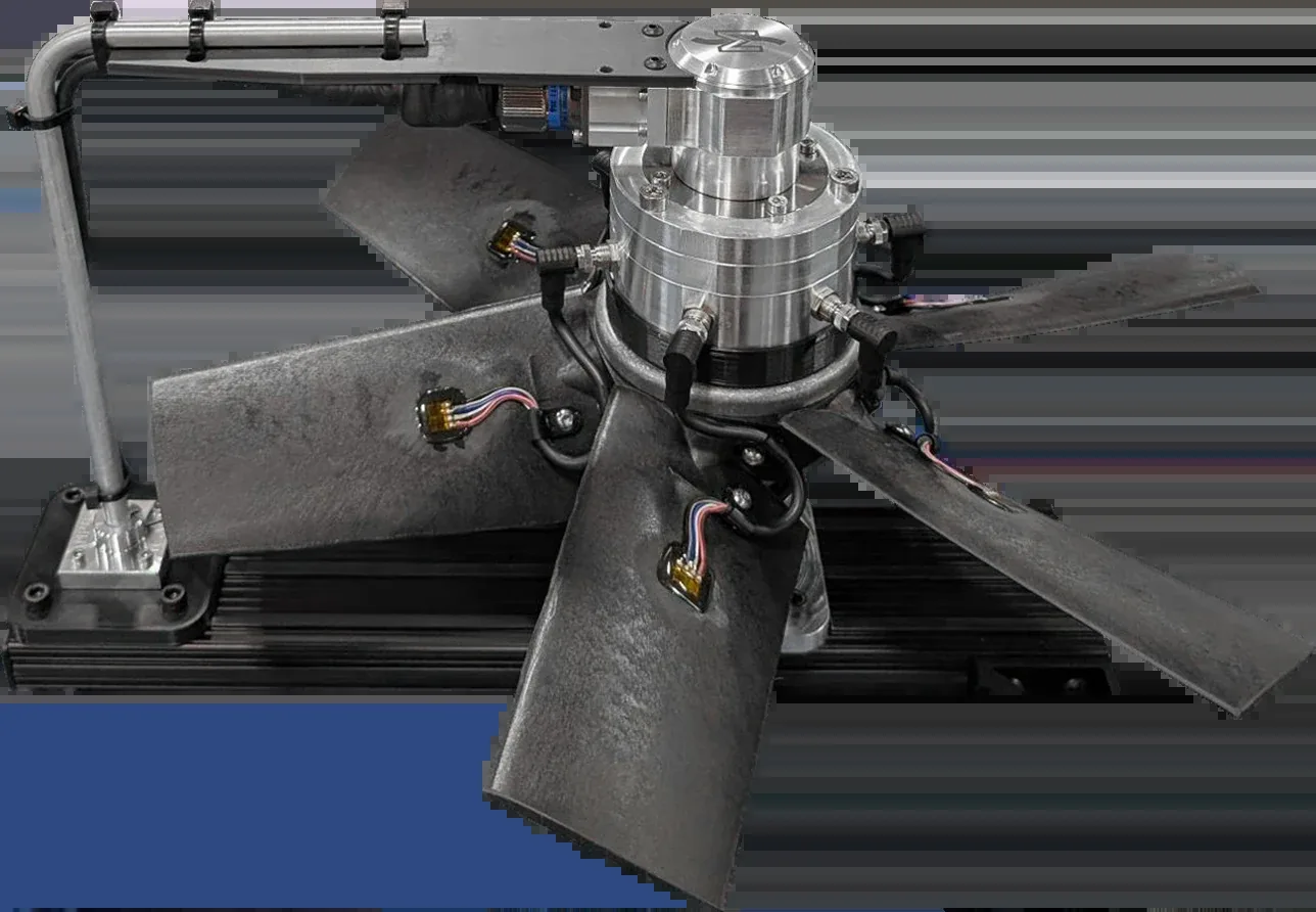 Turbines Fan and turbine blades Strain and temperature from many points on the blades, recorded together while the rotor turns.