
TR3D-B square three-axis load cell
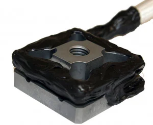
Square three-axis load cell for forces up to 1.1 kN per axis, in a body of 25.4 × 25.4 × 12.7 mm.
Square three-axis load cell for forces up to 4.4 kN per axis, in a body of 25.4 × 25.4 × 12.7 mm.
Square three-axis load cell for forces up to 17.7 kN per axis, in a body of 50.8 × 50.8 × 23.3 mm.
Square three-axis load cell for forces up to 20 kN per axis, in a body of 50.8 × 50.8 × 25.4 mm.
Square three-axis load cell for forces up to 22 kN in X and Y, 44 kN in Z, in a body of 43.2 × 43.2 × 27.0 mm.
Square three-axis load cell for forces up to 71 kN per axis, in a body of 101.5 × 101.5 × 46.7 mm.
- 1.1 kN
- Measuring range per axis
- 16 N·m
- Max moment per axis
- 3.5 mV/V
- Output
- 25.4 × 25.4 × 12.7 mm
- Dimensions
- 4.4 kN
- Measuring range per axis
- 65 N·m
- Max moment per axis
- 4.5 mV/V
- Output
- 25.4 × 25.4 × 12.7 mm
- Dimensions
- 17.7 kN
- Measuring range per axis
- 220 N·m
- Max moment per axis
- 4.5 mV/V
- Output
- 50.8 × 50.8 × 23.3 mm
- Dimensions
- 20 kN
- Measuring range per axis
- 220 N·m
- Max moment per axis
- XY 2.6 · Z 4.0 mV/V
- Output
- 50.8 × 50.8 × 25.4 mm
- Dimensions
- XY 22 kN · Z 44 kN
- Measuring range per axis
- 520 N·m
- Max moment per axis
- XY 2.0 · Z 4.0 mV/V
- Output
- 43.2 × 43.2 × 27.0 mm
- Dimensions
- 71 kN
- Measuring range per axis
- 1 700 N·m
- Max moment per axis
- 4.5 mV/V
- Output
- 101.5 × 101.5 × 46.7 mm
- Dimensions
- Non-linearity≤ 0.5 % FS
- Included3.05 m cable · ISO/IEC 17025 calibration report
- Non-linearity≤ 0.5 % FS
- Included3.05 m cable · ISO/IEC 17025 calibration report
- Non-linearity≤ 0.5 % FS
- Included3.05 m cable · ISO/IEC 17025 calibration report
- Non-linearity≤ 0.5 % FS
- Included6.1 m cable · ISO/IEC 17025 calibration report
- Range per axisFx 22 · Fy 22 · Fz 44 kN
- Body43.2 × 43.2 × 27 mm
- Non-linearity≤ 0.5 % FS
- Included3.05 m cable · ISO/IEC 17025 calibration report
- Non-linearity≤ 0.5 % FS
- Included3.05 m cable · ISO/IEC 17025 calibration report
TR3D-B-250: square three-axis load cell, 1.1 kN per axis
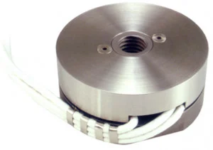
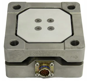
The TR3D-B-250 is a square three-axis load cell. Three four-arm strain gage bridges, one per axis, measure the forces in X, Y and Z, up to 1.1 kN (250 lbf) each; the maximum moment is 16 N·m per axis. The body measures 25.4 × 25.4 × 12.7 mm (1 × 1 × 0.5 in), is weatherproof sealed and temperature compensated. The full-scale output is 3.5 mV/V on all channels, nominal, with non-linearity and hysteresis below 0.5 % of full scale, at up to 10 V excitation, DC or AC rms. It is usable from −40 to 149 °C and comes with a 3.05 m shielded cable with open-ended leads.
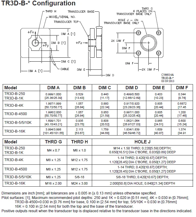
The top is fastened with a single M6 × 1.0 bolt and the base with four M4 × 0.7 bolts; where the base cannot be reached, an optional bottom thread adapter fixes it from above, through the top hole. Pilot surfaces on both faces locate the cell. Each bridge is powered separately on its own four leads (P+, S+, S−, P−). The cell is not intended for moments above 16 N·m per axis: several cells in an array between two stiff fixtures take them as forces. Each channel is calibrated to full scale, with an ISO/IEC 17025 calibration report that records cross-talk.
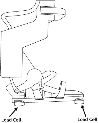
TR3D-B load cells are used where a load cell hardly fits, in robot arms and prosthetic feet, and on traction test fixtures to measure tire-road friction.
TR3D-B-1K: square three-axis load cell, 4.4 kN per axis
The TR3D-B-1K is a square three-axis load cell. Three four-arm strain gage bridges, one per axis, measure the forces in X, Y and Z, up to 4.4 kN (1,000 lbf) each; the maximum moment is 65 N·m per axis. The body measures 25.4 × 25.4 × 12.7 mm (1 × 1 × 0.5 in), is weatherproof sealed and temperature compensated. The full-scale output is 4.5 mV/V on all channels, nominal, with non-linearity and hysteresis below 0.5 % of full scale, at up to 10 V excitation, DC or AC rms. It is usable from −40 to 149 °C and comes with a 3.05 m shielded cable with open-ended leads.
The top is fastened with a single M6 × 1.0 bolt and the base with four M4 × 0.7 bolts; where the base cannot be reached, an optional bottom thread adapter fixes it from above, through the top hole. Pilot surfaces on both faces locate the cell. Each bridge is powered separately on its own four leads (P+, S+, S−, P−). The cell is not intended for moments above 65 N·m per axis: several cells in an array between two stiff fixtures take them as forces. Each channel is calibrated to full scale, with an ISO/IEC 17025 calibration report that records cross-talk.
It is used where a load cell hardly fits, inside robot arms, prosthetic feet and medical equipment.
TR3D-B-4K: square three-axis load cell, 17.7 kN per axis
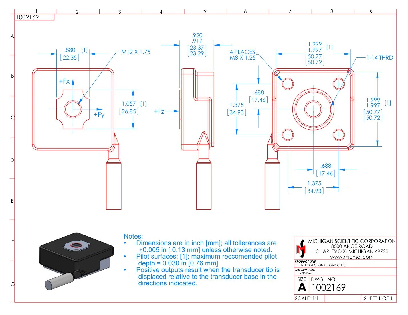
The TR3D-B-4K is a square three-axis load cell. Three four-arm strain gage bridges, one per axis, measure the forces in X, Y and Z, up to 17.7 kN (4,000 lbf) each; the maximum moment is 220 N·m per axis. The body measures 50.8 × 50.8 × 23.3 mm, is weatherproof sealed and temperature compensated. The full-scale output is 4.5 mV/V on all channels, nominal, with non-linearity and hysteresis below 0.5 % of full scale, at up to 10 V excitation, DC or AC rms. It is usable from −40 to 149 °C and comes with a 3.05 m shielded cable with open-ended leads.
The top is fastened with a single M12 × 1.75 bolt and the base with four M8 × 1.25 bolts; where the base cannot be reached, an optional bottom thread adapter fixes it from above, through the top hole. Pilot surfaces on both faces locate the cell. Each bridge is powered separately on its own four leads (P+, S+, S−, P−). The cell is not intended for moments above 220 N·m per axis: several cells in an array between two stiff fixtures take them as forces. Each channel is calibrated to full scale, with an ISO/IEC 17025 calibration report that records cross-talk.
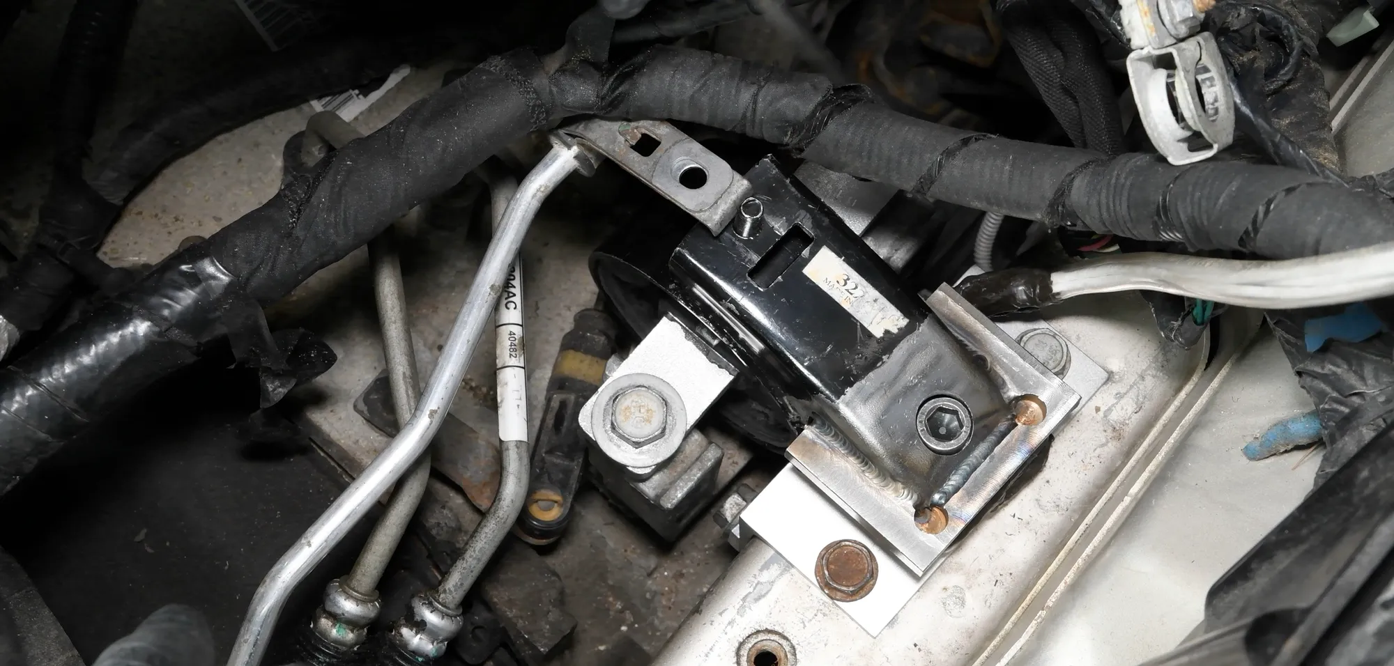
In a van test, a TR3D-B-4K in an adapter that replaced the production engine mount measured the three mount forces, with the engine kept in its position.
TR3D-B-4500: square three-axis load cell, 20 kN per axis
The TR3D-B-4500 is a square three-axis load cell. Three four-arm strain gage bridges, one per axis, measure the forces in X, Y and Z, up to 20 kN (4,500 lbf) each; the maximum moment is 220 N·m per axis. The body measures 50.8 × 50.8 × 25.4 mm, is weatherproof sealed and temperature compensated. The full-scale output is 2.6 mV/V in X and Y and 4.0 mV/V in Z, nominal, with non-linearity and hysteresis below 0.5 % of full scale, at up to 10 V excitation, DC or AC rms. It is usable from −40 to 149 °C and comes with a 6.1 m shielded cable with open-ended leads.
The top is fastened with a single M12 × 1.75 bolt and the base with four M8 × 1.25 bolts; where the base cannot be reached, an optional bottom thread adapter fixes it from above, through the top hole. Pilot surfaces on both faces locate the cell. Each bridge is powered separately on its own four leads (P+, S+, S−, P−). The cell is not intended for moments above 220 N·m per axis: several cells in an array between two stiff fixtures take them as forces. Each channel is calibrated to full scale, with an ISO/IEC 17025 calibration report that records cross-talk.
TR3D load cells are placed in adapters that replace production engine mounts, and bolted between a seat and its mountings, to measure the forces these parts carry in the vehicle.
TR3D-B-5/5/10K: square three-axis load cell, 22 kN in X and Y, 44 kN in Z
The TR3D-B-5/5/10K is a square three-axis load cell. Three four-arm strain gage bridges, one per axis, measure the forces in X, Y and Z, 22 kN (5,000 lbf) in X and Y and 44 kN (10,000 lbf) in Z; the maximum moment is 520 N·m per axis. The body measures 43.2 × 43.2 × 27.0 mm, is weatherproof sealed and temperature compensated. The full-scale output is 2.0 mV/V in X and Y and 4.0 mV/V in Z, nominal, with non-linearity and hysteresis below 0.5 % of full scale, at up to 10 V excitation, DC or AC rms. It is usable from −40 to 149 °C and comes with a 3.05 m shielded cable with open-ended leads.
The top is fastened with a single 5/8-18 (M16 × 2 on the -M16 and -M16T versions) bolt and the base with four M8 × 1.25 bolts; where the base cannot be reached, an optional bottom thread adapter fixes it from above, through the top hole. Pilot surfaces on both faces locate the cell. Each bridge is powered separately on its own four leads (P+, S+, S−, P−). The cell is not intended for moments above 520 N·m per axis: several cells in an array between two stiff fixtures take them as forces. Each channel is calibrated to full scale, with an ISO/IEC 17025 calibration report that records cross-talk.
TR3D load cells are bolted between a seat and its mountings to measure the forces they carry while driving and in a crash.
TR3D-B-16K: square three-axis load cell, 71 kN per axis
The TR3D-B-16K is a square three-axis load cell. Three four-arm strain gage bridges, one per axis, measure the forces in X, Y and Z, up to 71 kN (16,000 lbf) each; the maximum moment is 1.7 kN·m per axis. The body measures 101.5 × 101.5 × 46.7 mm, is weatherproof sealed and temperature compensated. The full-scale output is 4.5 mV/V on all channels, nominal, with non-linearity and hysteresis below 0.5 % of full scale, at up to 10 V excitation, DC or AC rms. It is usable from −40 to 149 °C and comes with a 3.05 m shielded cable with open-ended leads.
The top is fastened with a single M24 × 3.0 bolt and the base with four M16 × 2.0 bolts; where the base cannot be reached, an optional bottom thread adapter fixes it from above, through the top hole. Pilot surfaces on both faces locate the cell. Each bridge is powered separately on its own four leads (P+, S+, S−, P−). The cell is not intended for moments above 1.7 kN·m per axis: several cells in an array between two stiff fixtures take them as forces. Each channel is calibrated to full scale, with an ISO/IEC 17025 calibration report that records cross-talk.
Several TR3D load cells are used in arrays between two stiff fixtures when the combined load exceeds the capacity of a single cell; their capacities add along each axis.
Specifications
| Measured quantities | Fx · Fy · Fz |
|---|---|
| Force capacity | Fx 1.1 · Fy 1.1 · Fz 1.1 kN |
| Moment capacity | 16 N·m (max per axis) |
| Non-linearity | ≤ 0.5 % FS |
| Hysteresis | ≤ 0.5 % FS |
| Axes | 3 (orthogonal) |
| Sensing principle | Strain gage (3 four-arm bridges) |
| Rated output | 3.5 mV/V |
| Excitation voltage | 10 V (max, DC or AC rms) |
| Load thread | M6 × 1.0 |
| Mounting fasteners | 4 × M4 × 0.7 (and M14 × 1.5) |
| Dimensions | 25.4 × 25.4 × 12.7 mm |
| Material | Stainless steel · Aluminum |
| Operating temperature | −40 to 149 °C |
| Connections | Cable (shielded, open-ended leads) |
| Cable length | 3.05 m |
| Measured quantities | Fx · Fy · Fz |
|---|---|
| Force capacity | Fx 4.4 · Fy 4.4 · Fz 4.4 kN |
| Moment capacity | 65 N·m (max per axis) |
| Non-linearity | ≤ 0.5 % FS |
| Hysteresis | ≤ 0.5 % FS |
| Axes | 3 (orthogonal) |
| Sensing principle | Strain gage (3 four-arm bridges) |
| Rated output | 4.5 mV/V |
| Excitation voltage | 10 V (max, DC or AC rms) |
| Load thread | M6 × 1.0 |
| Mounting fasteners | 4 × M4 × 0.7 (and M14 × 1.5) |
| Dimensions | 25.4 × 25.4 × 12.7 mm |
| Material | Stainless steel · Aluminum |
| Operating temperature | −40 to 149 °C |
| Connections | Cable (shielded, open-ended leads) |
| Cable length | 3.05 m |
| Measured quantities | Fx · Fy · Fz |
|---|---|
| Force capacity | Fx 17.7 · Fy 17.7 · Fz 17.7 kN |
| Moment capacity | 220 N·m (max per axis) |
| Non-linearity | ≤ 0.5 % FS |
| Hysteresis | ≤ 0.5 % FS |
| Axes | 3 (orthogonal) |
| Sensing principle | Strain gage (3 four-arm bridges) |
| Rated output | 4.5 mV/V |
| Excitation voltage | 10 V (max, DC or AC rms) |
| Load thread | M12 × 1.75 |
| Mounting fasteners | 4 × M8 × 1.25 (and 1-14) |
| Dimensions | 50.8 × 50.8 × 23.3 mm |
| Material | Stainless steel · Aluminum |
| Operating temperature | −40 to 149 °C |
| Connections | Cable (shielded, open-ended leads) |
| Cable length | 3.05 m |
| Measured quantities | Fx · Fy · Fz |
|---|---|
| Force capacity | Fx 20 · Fy 20 · Fz 20 kN |
| Moment capacity | 220 N·m (max per axis) |
| Non-linearity | ≤ 0.5 % FS |
| Hysteresis | ≤ 0.5 % FS |
| Axes | 3 (orthogonal) |
| Sensing principle | Strain gage (3 four-arm bridges) |
| Rated output | Fx 2.6 · Fy 2.6 · Fz 4 mV/V |
| Excitation voltage | 10 V (max, DC or AC rms) |
| Load thread | M12 × 1.75 |
| Mounting fasteners | 4 × M8 × 1.25 (and 1-14) |
| Dimensions | 50.8 × 50.8 × 25.4 mm |
| Material | Stainless steel · Aluminum |
| Operating temperature | −40 to 149 °C |
| Connections | Cable (shielded, open-ended leads) |
| Cable length | 6.1 m |
| Measured quantities | Fx · Fy · Fz |
|---|---|
| Force capacity | Fx 22 · Fy 22 · Fz 44 kN |
| Moment capacity | 520 N·m (max per axis) |
| Non-linearity | ≤ 0.5 % FS |
| Hysteresis | ≤ 0.5 % FS |
| Axes | 3 (orthogonal) |
| Sensing principle | Strain gage (3 four-arm bridges) |
| Rated output | Fx 2 · Fy 2 · Fz 4 mV/V |
| Excitation voltage | 10 V (max, DC or AC rms) |
| Load thread | 5/8-18 (M16 × 2 on -M16 and -M16T) |
| Mounting fasteners | 4 × M8 × 1.25 |
| Dimensions | 43.2 × 43.2 × 27 mm |
| Material | Stainless steel · Aluminum |
| Operating temperature | −40 to 149 °C |
| Connections | Cable (shielded, open-ended leads) |
| Cable length | 3.05 m |
| Measured quantities | Fx · Fy · Fz |
|---|---|
| Force capacity | Fx 71 · Fy 71 · Fz 71 kN |
| Moment capacity | 1 700 N·m (max per axis) |
| Non-linearity | ≤ 0.5 % FS |
| Hysteresis | ≤ 0.5 % FS |
| Axes | 3 (orthogonal) |
| Sensing principle | Strain gage (3 four-arm bridges) |
| Rated output | 4.5 mV/V |
| Excitation voltage | 10 V (max, DC or AC rms) |
| Load thread | M24 × 3.0 |
| Mounting fasteners | 4 × M16 × 2.0 |
| Dimensions | 101.5 × 101.5 × 46.7 mm |
| Material | Stainless steel · Aluminum |
| Operating temperature | −40 to 149 °C |
| Connections | Cable (shielded, open-ended leads) |
| Cable length | 3.05 m |
Connectors and cable length can be specified when ordering.
Used with the TR3D-B
What you add here goes into the same quote request.
-
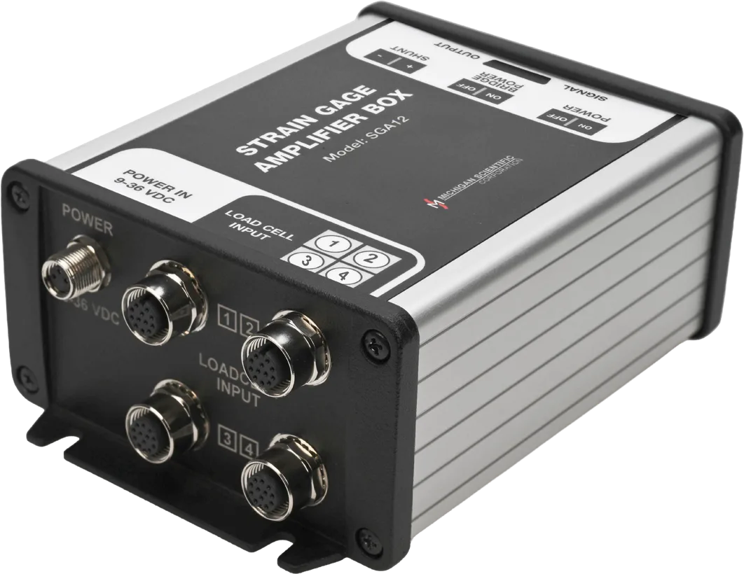
Read the three axes as ± 10 V
SGA3, the three-channel model of the SGA series
± 5 V bridge excitation, a ± 10 V output per axis and shunt calibration from a switch on the box.
One SGA3 per load cell.
-
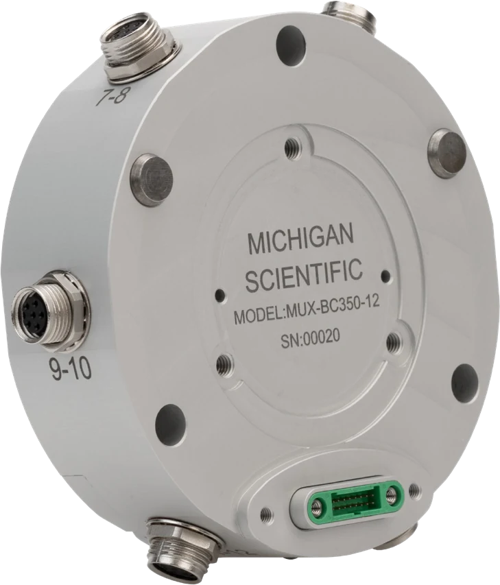
Log every axis on one CAN bus
MUX-FB-12, the full-bridge module of the MUX-12 series
Twelve full-bridge inputs, one CAN 2.0 or CAN FD output up to 8 ksps, integrated shunt resistors for calibration.
Twelve channels per module; up to four modules stack for 48 synchronized channels.
Resources
Datasheets and manuals
Drawings
CAD models
Datasheets and manuals
Drawings
CAD models
Datasheets and manuals
Drawings
CAD models
Datasheets and manuals
Drawings
CAD models
Datasheets and manuals
Drawings
CAD models
Datasheets and manuals
Drawings
None for TR3D-B-16K.
CAD models
Related applications
- Component Engine mount loads The three forces each mount passes to the frame during start-up, acceleration and gear shifts.
-
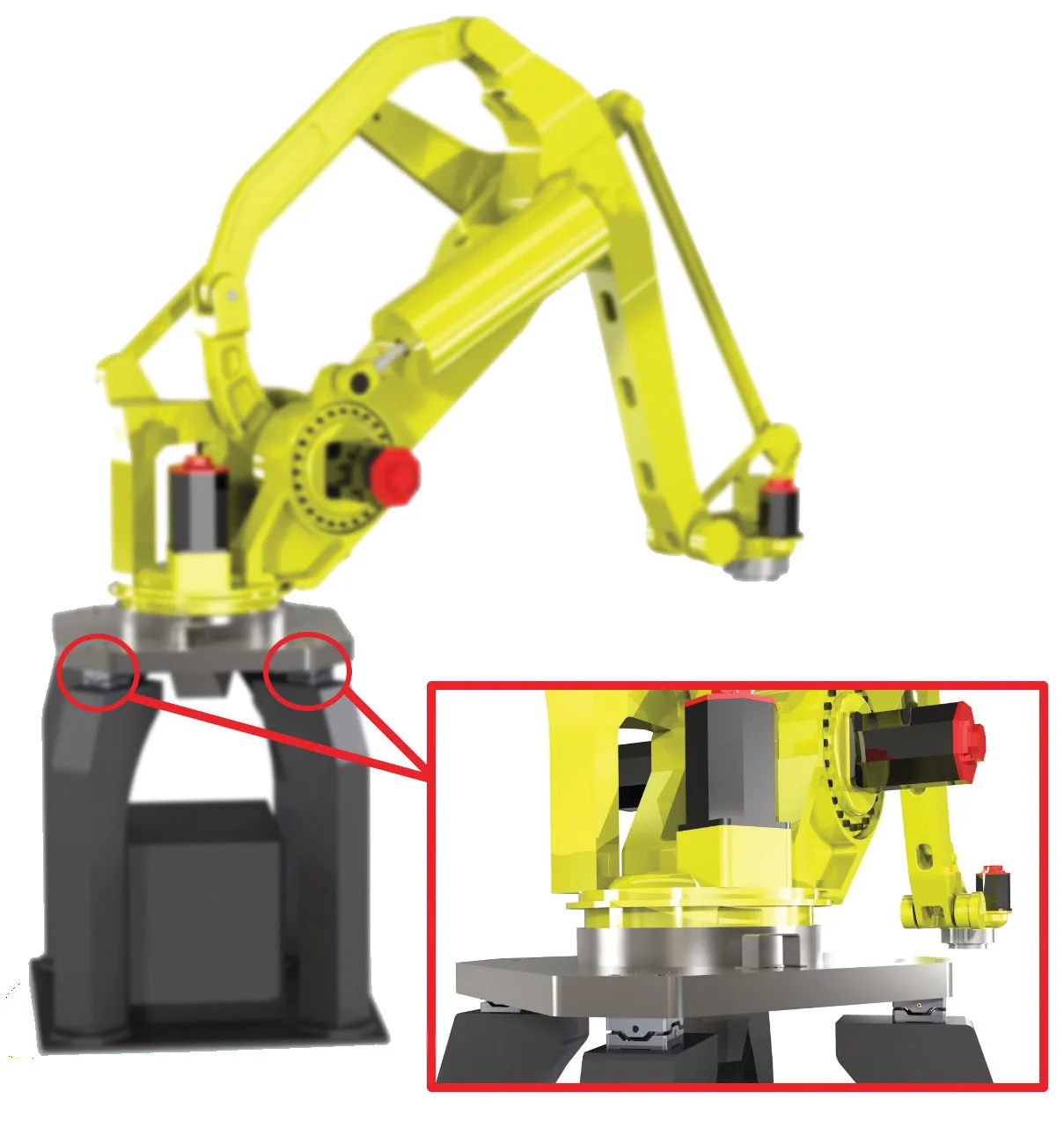 Component Robotics and prosthetics Forces in three directions, and moments, on a robot arm or a prosthetic foot, from a load cell small enough to fit in the assembly.
-
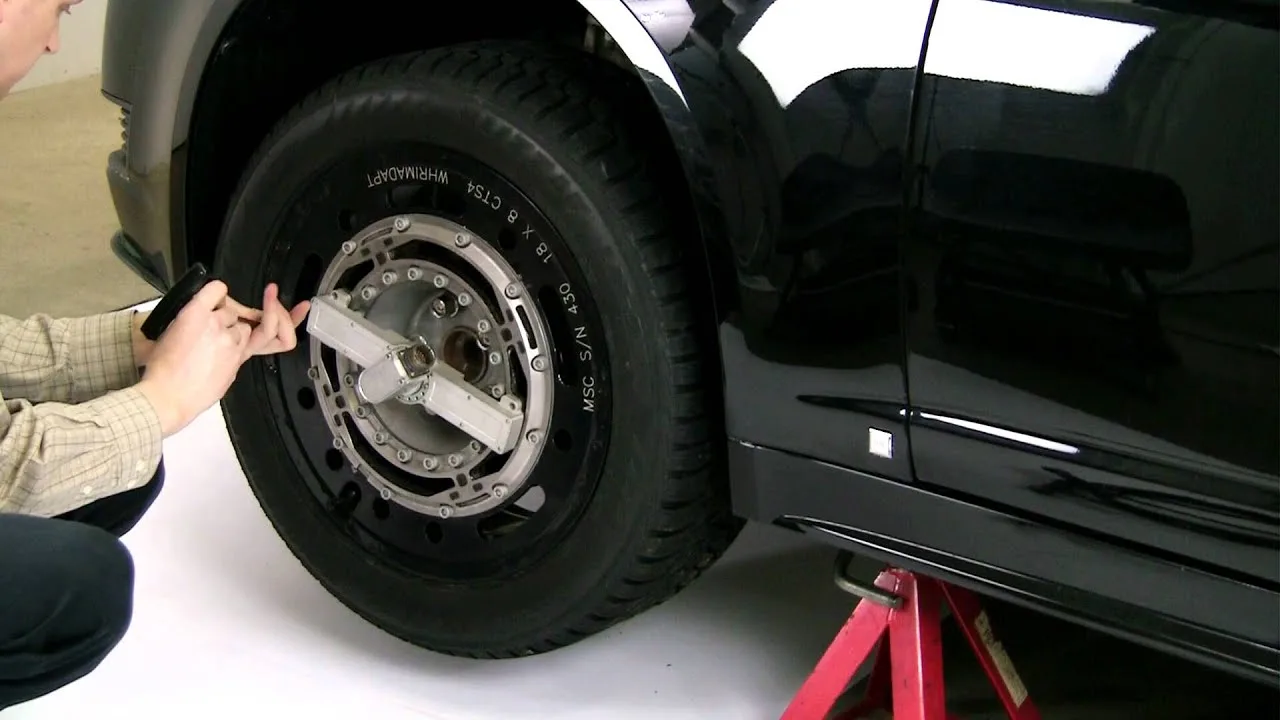 Tires Tire-road friction Tire and road surface forces measured in three directions on a traction fixture, to find the coefficient of friction.
-
 Medical Medical equipment Small tension loads, multi-axis forces on prostheses and clean temperature signals, for medical and pharmaceutical equipment.
A question on this product?
Load range per axis, mounting, test type. An application engineer answers.
More details to give? Use the full contact form.