
Custom development
Your part is the transducer.
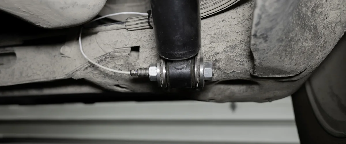
Tie rods, shear pins, hubs, wheels: production parts strain gaged and calibrated, so nothing sits between the load and the measurement.
No adapter, no added mass, no change of geometry under the vehicle. Michigan Scientific has gaged tie rods, half shafts, pedals and hitches for decades; our engineers scope it with you and run the project.
- 0 adapters
- The production part itself is gaged
- 4 steps
- Load case, design, strain gaging, calibration
- 6 to 8 weeks
- Typical lead time for a gaged tie rod
- ISO/IEC 17025
- Calibration of the finished transducer
What we build
- Tie rod end transducers Replaces the inner or outer tie rod end, from your production tie rod. Axial force during steering, with no extra space under the vehicle.
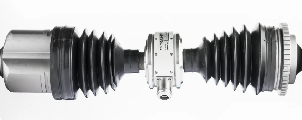
- Strain gaged half shafts and propshafts Your shaft, gaged and calibrated on a precision torque machine, with the slip ring or telemetry to bring the signal off.
- Wheel instrumentation Gages, thermocouples, speed and acceleration from the wheel, brake, tire, hub or axle, through a waterproof wheel package. Forklifts to Class 8 tractors.
- Shear pins and hitch transducers Suspension links, pintle hitches, towing eyes: force where the part already carries it.
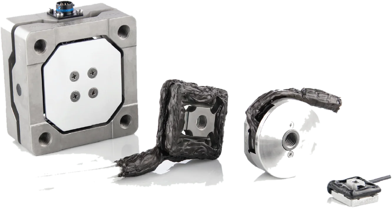
- Custom slip rings and wheel transducers A slip ring to your bore and circuit count; a wheel force transducer for an unusual bolt pattern, motorsport hub or agricultural wheel.
Three builds
Need, answer, result. Figures are the published ones; customer names stay out unless agreed.
- Steering · passenger car
A tie rod that measures itself
Need. Record tie rod forces during steering to feed and verify the vehicle model, without changing the suspension geometry.
Answer. The production tie rod end gaged and calibrated, positioned from experience on hundreds of tie rods; no vehicle modification.
Result. axial force in the simulation loop · 0 mm added under the car
- Towing · heavy and military vehicles
Forces on a pintle hitch
Need. Measure the three forces and the moment at the hitch of a towing vehicle, in the field.
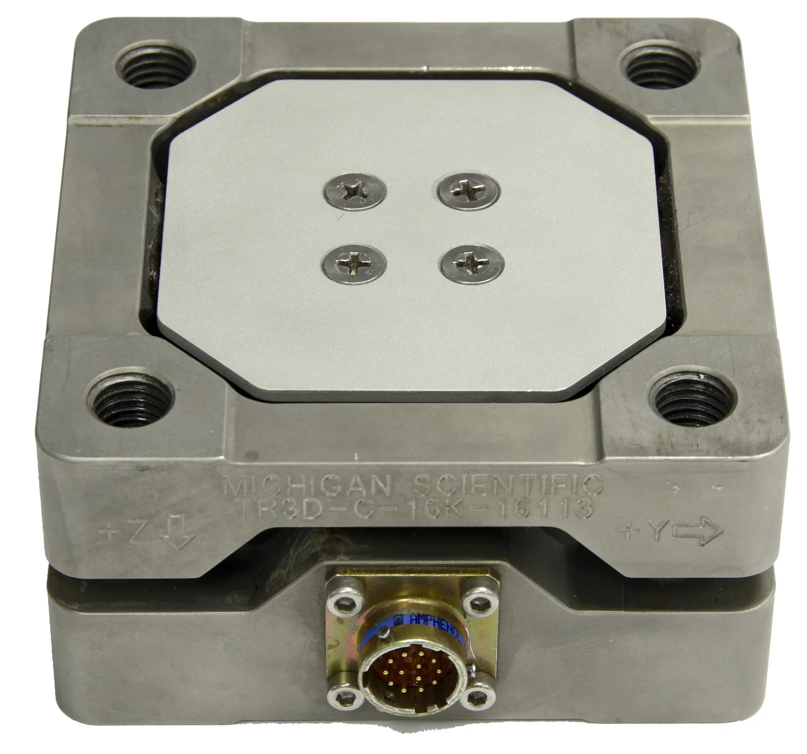
Answer. A TR3D-C-40K three-axis load cell fitted into the hitch mount.
Result. 177 kN (40 000 lb) · 10.8 kN·m (8 000 lb·ft)
- Powertrain · front-wheel drive
Torque through a half shaft
Need. Validate driveline loads on the vehicle, on a shaft with no room for a conventional torque transducer.
Answer. Deep-bore gaging of the customer shaft, calibration, then a weatherproof tubular slip ring or a CIT telemetry clamped on.
Result. strain gaged production shaft · slip ring or 2.4 GHz telemetry
From your drawing to a calibrated part.
- 01
Load case
You send the part or its drawing, the loads, the environment. We say whether the part can become a transducer and at what accuracy.
- 02
Design
Gage placement from FEA and experience, wiring route, sealing, how the signal leaves the part.
- 03
Strain gaging
Gaging, wiring and protection at the Michigan Scientific factory, on your part or on parts we supply.
- 04
Calibration
The finished transducer calibrated in the accredited laboratory, certificate and sensitivity delivered with it.
What we need to quote: the part or its drawing, the expected loads and their direction, the environment, the number of units, and how the signal leaves the part.
A part to instrument?
Send the drawing and the load case. An application engineer answers with a feasibility and a first price.
More details to give? Use the full contact form.