Application · Turbines
Measuring strain and temperature on fan and turbine blades while the rotor turns
In brief
Blade tests on fans and turbines need many sensors on the rotor: strain gages or thermocouples on several blades, or at several points on one blade. All these signals have to leave the rotating part together. A slip ring with 45 or 60 circuits on the end of the shaft carries them to a stationary recorder. Telemetry on the rotating part does the same without contact, with amplifiers next to the sensors.
- 45 or 60
- circuits on one end-of-shaft slip ring
- 4 000 rpm
- maximum speed of the SR45A-AXHS and SR60A-AXHS
- 8
- thermocouple or strain gage channels on the Model T8 telemetry
Why blades are instrumented while they turn
Blade strain and temperature are measured during operation, with the rotor turning. Strain gages and thermocouples on the blades are wired through a slip ring, or read by a telemetry system on the rotor. The recorded data is then examined for high strains and abnormal temperatures.
Aircraft turbine components run in a severe environment and are asked for more and more power, so their rotating parts are tested regularly.
Many signals, and one shaft to bring them out
The first constraint is the channel count. Each strain gage or thermocouple needs its own connections, and a test that covers several blades soon asks for dozens of circuits between the rotor and the stationary recorder.
The second is noise. On a jet engine turbine, the operating conditions add noise to low-level strain and thermocouple signals. Amplifying them on the rotor, close to the sensors, reduces the errors caused by temperature gradients across the dissimilar metals of the slip ring and by magnetic interference.
A slip ring with 45 or 60 circuits on the shaft end
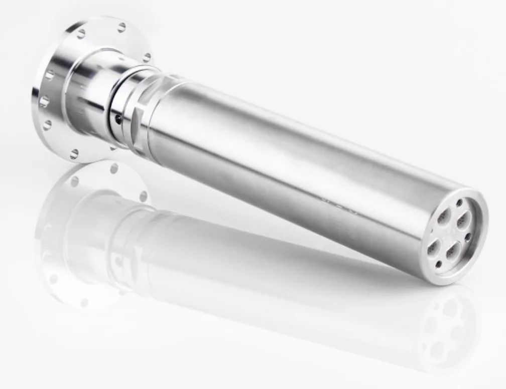
The SR45A-AXHS and SR60A-AXHS slip rings mount on the end of the rotating shaft. They give 45 or 60 connections to strain gages, thermocouples and other sensors, through circular connectors on the rotor and on the stator. They are rated for 4 000 rpm. Brushes and rings are in wrought precious metals with no plating, which keeps the resistance variation low enough for low-level signals. The bearings are lubricated for life, so no routine maintenance is needed.
- 01
Decide the sensor layout
Gages or thermocouples go at the areas of interest: on several blades, or at many points on one blade. The layout sets the number of circuits, and so the choice between 45 and 60.
- 02
Route the wires to the shaft end
The sensor wires are brought to the rotor connectors of the slip ring, mounted on the end of the shaft.
SR45A-AXHS and SR60A-AXHS - 03
Record on the stationary side
The stator connectors go to the data acquisition system, which records all the channels together during the run.
- 04
Or use telemetry
A telemetry system mounted on the rotating component sends strain gage or thermocouple signals without contact. It is powered by battery or by induction.
Wireless telemetry systems
Wind turbines: blades and gearbox
On wind turbines, Michigan Scientific slip ring assemblies are used in the gearbox and on the blades. Strain gages are placed on several blades or at many points on one blade, and the slip ring carries the strain signals to the stationary data acquisition system.
Jet turbines: thermocouples, amplifiers and telemetry
The same principle applies to jet turbine testing. When the test needs temperatures from several spots on the turbine, or from several blades, the thermocouple signals are routed to the high channel count slip ring. Its operating temperature range is −40 to 121 °C.
Telemetry is the other route. The transmitter is mounted on the rotating components, with thermocouple and strain gage amplifiers that raise the signals to a high level before transmission. On the Model T8, the eight channels go out digitally by RF with error checking, and the receiver gives a ±10 V analog output per channel, read during the run.
What you get
Strain and temperature from many points on the rotor, recorded together during operation. The data shows where strains are high and where temperatures are abnormal. The transmission is chosen for the channel count, the speed and the environment: a 45 or 60 circuit slip ring, or telemetry.
Frequent questions
How do you get strain gage signals off a rotating turbine blade?
Through a slip ring on the end of the shaft, or through telemetry mounted on the rotating part. The slip ring carries the gage circuits to a stationary data acquisition system, which records all the channels together during the run.
How many circuits can a slip ring carry for blade measurements?
The SR45A-AXHS gives 45 connections and the SR60A-AXHS gives 60, through circular connectors on the rotor and on the stator. The sensor layout sets the number of circuits needed, since each strain gage or thermocouple needs its own connections.
What is the maximum speed of a 45 or 60 circuit slip ring?
The SR45A-AXHS and SR60A-AXHS slip rings are rated for 4 000 rpm. Their operating temperature range is −40 to 121 °C.
When is telemetry used instead of a slip ring on a turbine?
Telemetry sends strain gage or thermocouple signals without contact, powered by battery or by induction. On a jet turbine, the transmitter is mounted on the rotating components with its amplifiers, so the low-level signals are amplified on the rotor before they are transmitted.