
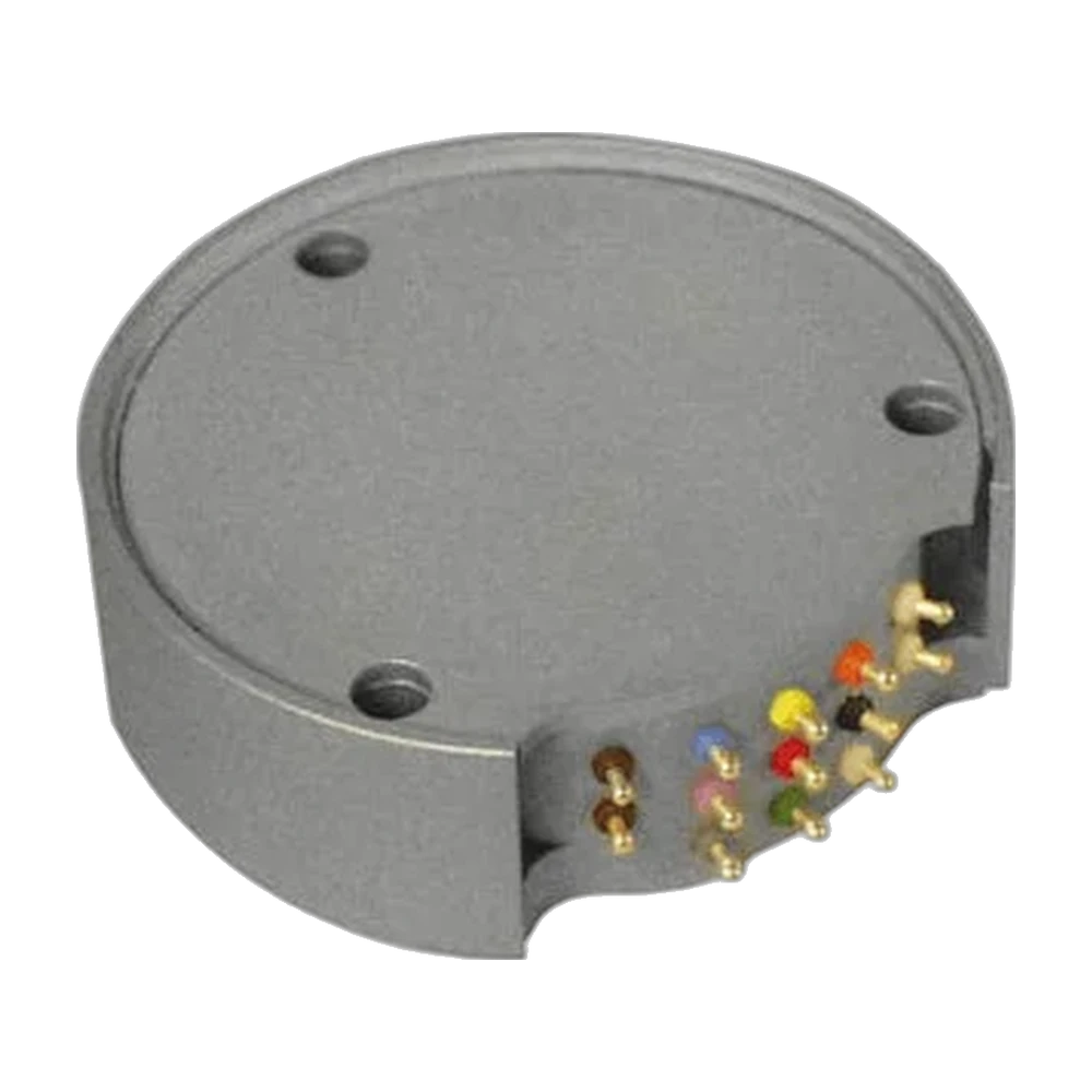
AMP-SG-U2 series spinning strain gage amplifiers, 1 to 3 channels
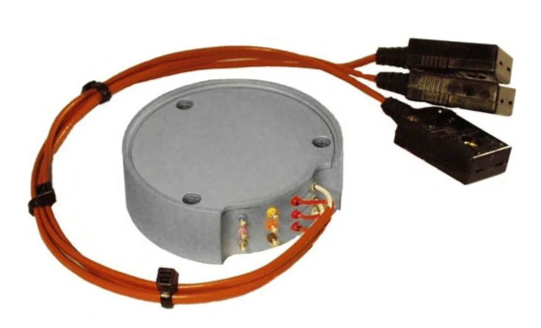
Spinning strain gage amplifier modules for one, two or three bridges, Ø 53 mm, piloted on the rotor of SR series slip rings and stackable, with ± 10 V output.
Model AMP-SG-U2
- 1
- Bridge channel
- 10 kHz
- Bandwidth, gain 100
- ± 2.5 to ± 10 V
- Bridge excitation
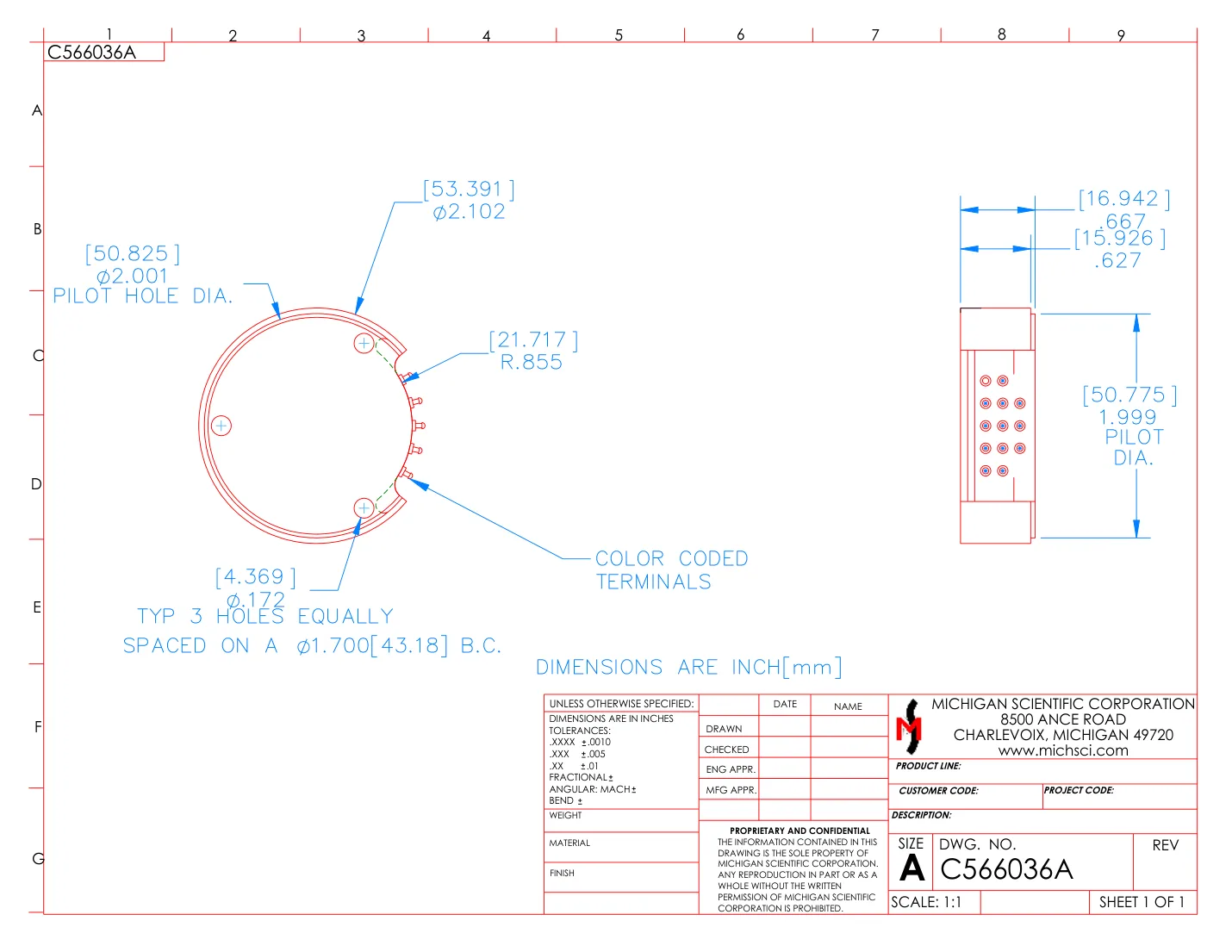
- Ø 53.39 × 16.94 mm
- Module
- 2
- Bridge channels
- 20 kHz
- Bandwidth
- ± 2.5 or ± 5 V
- Bridge excitation
- Ø 53.37 × 15.75 mm
- Module
- 3
- Bridge channels
- 20 kHz
- Bandwidth
- ± 2.5 or ± 5 V
- Bridge excitation
- Ø 53.37 × 21.46 mm
- Module
- Gain100 to 2000 V/V
- Output± 10 V
- Bridge excitation± 2.5 V standard; ± 5 V, ± 8.5 V or ± 10 V to order
- Gain100 to 2000 V/V
- Output± 10 V
- Bridge excitation± 2.5 V standard; ± 5 V, ± 8.5 V or ± 10 V to order
- Gain100 to 2000 V/V
- Output± 10 V
- Bridge excitation± 2.5 V standard; ± 5 V, ± 8.5 V or ± 10 V to order
Mounted on the slip ring rotor
The AMP-SG-U2 series are modular spinning strain gage amplifiers that pilot on the rotor of Michigan Scientific SR series slip rings: AMP-SG-U2 for one bridge, AMP-SG2-U2 for two, AMP-SG3-U2 for three. Each channel has low-drift bipolar bridge excitation, a low-noise differential amplifier, gain 100 to 2000 V/V set by jumper or external resistor, remote positive or negative shunt calibration and a ± 10 V output.
AMP-SG-U2: excitation ± 2.5 V as standard, ± 5, ± 8.5 or ± 10 V on the -10, -17 and -20 versions; −3 dB at 10 kHz at gain 100, 1 kHz at gain 1000, higher on request; supply ± 13 to ± 17 V DC; Ø 53.39 × 16.94 mm, 64 or 82 g. AMP-SG3-U2: excitation ± 2.5 V on -5 or ± 5 V on -10; 20 kHz at gains 100 and 1000; supply ± 15 V DC, ± 45 mA plus bridge load; −40 to 125 °C; Ø 53.37 × 21.46 mm, 68.5 g. AMP-SG2-U2: excitation ± 2.5 V on -5 or ± 5 V on -10; 20 kHz at gains 100 and 1000; supply ± 15 V DC, ± 30 mA plus bridge load; −40 to 125 °C; Ø 53.37 × 15.75 mm, 51.3 g. The two- and three-channel models take bridges of 350 Ω or more, the single-channel model 120 Ω or more.
Modules pilot on a 50.77 mm diameter, machined at least 1.27 mm deep, are held by three screws on a 43.18 mm bolt circle and stack, or array around an adapter plate, for more channels. Wires are soldered to color-coded terminals. A PS series power supply provides the supply, turns the bridge excitation off and applies the shunt calibration. With three-channel modules, a twenty-circuit slip ring carries up to 15 data channels.
Specifications
| Channels | 1 |
|---|---|
| Input | Strain gage bridge (full bridge) |
| Output | Analog voltage |
| Output range | −10 to 10 V |
| Bandwidth | 10 kHz (−3 dB at gain 100; 1 kHz at gain 1000; higher on request) |
| Noise, referred to input | ≤ 0.7 µV (p-p, 0.01 to 10 Hz) |
| Gain | 100 to 2 000 V/V (100 or 2000 by jumper, any value between by external resistor) |
| Gain setting | Jumper · External resistor |
| Shunt calibration | Positive · Negative · Remote |
| Shunt resistor | 100 · 1 000 kΩ (internal; 100 kΩ to 1 MΩ external) |
| Gain accuracy | ≤ 0.5 % (typical: 0.05 % at gain 100, 0.50 % at gain 1000) |
| Gain temperature coefficient | ≤ 0.0025 %/°C |
| Input offset | ≤ 10 µV |
| Offset drift | ≤ 0.1 µV/°C (1.0 µV/month) |
| CMRR | 160 dB |
| Slew rate | 0.5 V/µs |
| Settling time | 145 µs (to 0.01 %, gain 100) |
| Shunt accuracy | ≤ 0.1 % (0.02 % at 100 kΩ, 0.10 % at 1 MΩ) |
| Supply voltage | 13 to 17 V (dual supply, ± 13 to ± 17 V DC) |
| Excitation voltage | 5 to 20 V (± 2.5 V standard, ± 5 V on -10, ± 8.5 V on -17, ± 10 V on -20, bipolar DC constant voltage; others on request; remote on/off) |
| Bridge resistance | 120 Ω (minimum) |
| Supply current | 15 mA (per rail, plus bridge load; + 15 mA during shunt calibration) |
| Excitation current limit | 42 mA (standard; 84 mA on -10, 142 mA on -17, 167 mA on -20) |
| Max capacitive load | 1 000 pF |
| Excitation accuracy | ≤ 0.4 % |
| Excitation temperature coefficient | ≤ 0.0005 %/°C |
| Mounting | Bolted (pilots on SR series slip ring rotors, stackable) |
| Mounting fasteners | 3 × Ø 4.37 mm (through holes) |
| Bolt circle | 43.18 mm |
| Pilot diameter | 50.77 mm (1.27 mm deep) |
| Dimensions | Ø 53.39 × 16.94 mm |
| Weight | 64 g (standard and -10; 82 g for -17 and -20) |
| Operating temperature | −55 to 125 °C |
| Compensated temperature | −25 to 85 °C |
| Connections | Solder terminals (color-coded) |
| Channels | 2 |
|---|---|
| Input | Strain gage bridge (full bridge) |
| Output | Analog voltage |
| Output range | −10 to 10 V |
| Bandwidth | 20 kHz (−3 dB at gain 100 and 1000) |
| Noise, referred to input | ≤ 0.7 µV (p-p, 0.01 to 10 Hz) |
| Gain | 100 to 2 000 V/V (100 or 2000 by jumper, any value between by external resistor) |
| Gain setting | Jumper · External resistor |
| Shunt calibration | Positive · Negative · Remote |
| Shunt resistor | 100 · 1 000 kΩ (internal; 100 kΩ to 1 MΩ external) |
| Gain accuracy | ≤ 0.5 % (typical: 0.05 % at gain 100, 0.50 % at gain 1000) |
| Gain temperature coefficient | ≤ 0.0025 %/°C |
| Input offset | ≤ 10 µV (typical; 50 µV max) |
| Offset drift | ≤ 0.1 µV/°C (typical, 0.25 µV/°C max; 0.1 µV/month) |
| CMRR | 160 dB |
| Slew rate | 4 V/µs |
| Settling time | 9 µs (to 0.01 %, gain 100) |
| Shunt accuracy | ≤ 0.1 % |
| Supply voltage | 15 V (dual supply, ± 15 V DC) |
| Excitation voltage | 5 to 10 V (± 2.5 V on -5, ± 5 V on -10, bipolar DC constant voltage; remote on/off) |
| Bridge resistance | 350 Ω (minimum) |
| Supply current | 30 mA (per rail, plus bridge load; + 20 mA during shunt calibration) |
| Excitation current limit | 42 mA (-5; 84 mA on -10) |
| Max capacitive load | 1 000 pF |
| Excitation accuracy | ≤ 0.4 % |
| Excitation temperature coefficient | ≤ 0.0005 %/°C |
| Mounting | Bolted (pilots on SR series slip ring rotors, stackable) |
| Dimensions | Ø 53.37 × 15.75 mm |
| Weight | 51.3 g |
| Operating temperature | −40 to 125 °C |
| Compensated temperature | −40 to 85 °C |
| Connections | Solder terminals (color-coded) |
| Channels | 3 |
|---|---|
| Input | Strain gage bridge (full bridge) |
| Output | Analog voltage |
| Output range | −10 to 10 V |
| Bandwidth | 20 kHz (−3 dB at gain 100 and 1000) |
| Noise, referred to input | ≤ 0.7 µV (p-p, 0.01 to 10 Hz) |
| Gain | 100 to 2 000 V/V (100 or 2000 by jumper, any value between by external resistor) |
| Gain setting | Jumper · External resistor |
| Shunt calibration | Positive · Negative · Remote |
| Shunt resistor | 100 · 1 000 kΩ (internal; 100 kΩ to 1 MΩ external) |
| Gain accuracy | ≤ 0.5 % (typical: 0.05 % at gain 100, 0.50 % at gain 1000) |
| Gain temperature coefficient | ≤ 0.0025 %/°C |
| Input offset | ≤ 10 µV (typical; 50 µV max) |
| Offset drift | ≤ 0.1 µV/°C (typical, 0.25 µV/°C max; 0.1 µV/month) |
| CMRR | 160 dB |
| Slew rate | 4 V/µs |
| Settling time | 9 µs (to 0.01 %, gain 100) |
| Shunt accuracy | ≤ 0.1 % |
| Supply voltage | 15 V (dual supply, ± 15 V DC) |
| Excitation voltage | 5 to 10 V (± 2.5 V on -5, ± 5 V on -10, bipolar DC constant voltage; remote on/off) |
| Bridge resistance | 350 Ω (minimum) |
| Supply current | 45 mA (per rail, plus bridge load; + 30 mA during shunt calibration) |
| Excitation current limit | 42 mA (-5; 84 mA on -10) |
| Max capacitive load | 1 000 pF |
| Excitation accuracy | ≤ 0.4 % |
| Excitation temperature coefficient | ≤ 0.0005 %/°C |
| Mounting | Bolted (pilots on SR series slip ring rotors, stackable) |
| Dimensions | Ø 53.37 × 21.46 mm |
| Weight | 68.5 g |
| Operating temperature | −40 to 125 °C |
| Compensated temperature | −40 to 85 °C |
| Connections | Solder terminals (color-coded) |
Request a quote
Resources
Datasheets and manuals
CAD models
Datasheets and manuals
CAD models
Datasheets and manuals
Drawings
CAD models
In the same family
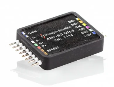
- One channel, 11 g AMP-SG-MH
One bridge channel, 11 g, mounting bracket available.
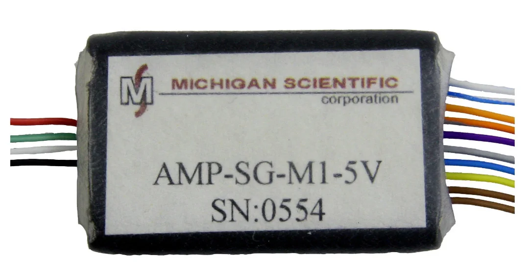
- One channel, wired AMP-SG-M1
One bridge channel, 14 g, wired connections.
- Thermocouples instead AMP-TCN-X2
Up to nine thermocouple channels on the rotor of an SR slip ring.
A question on this product?
Describe the measurement. An application engineer answers.
More details to give? Use the full contact form.