
Application · Engine
Measuring torque and strain on a production crankshaft with the engine running
In brief
Crankshaft measurements check the strength of the shaft in the running engine and give test data to verify simulations. A production crankshaft is fitted with strain gages at locations chosen on the customer's solid model, so the shaft itself becomes the transducer. A slip ring or a telemetry system brings the signals out of the engine. The test runs with the engine in the vehicle or on a dynamometer.
Why measure on the crankshaft itself
Strain gages on the crankshaft itself measure the loads the shaft carries in the running engine. The data check its strength and are compared with simulation results.
The most useful single channel is usually the output torque, measured near the main journal bearing at the flywheel end. It is a direct measurement of the torque going into the transmission, and it also serves the study of the whole drivetrain.
Every engine is different
There is no standard crankshaft transducer, because engine designs differ too much. Michigan Scientific has instrumented crankshafts from small motorcycle engines up to large 12-liter engines. Each job is designed around one engine.
Space is the second constraint. The gages, the wiring and the signal transmission all have to fit in the engine, and the layout is not the same in a vehicle as on a dynamometer. Where the test will run has to be known before the layout is drawn.
From the solid model to the gaged shaft
The work starts on the customer's solid models or cross sections, well before a gage is applied.
- 01
Choose the gage locations on the model
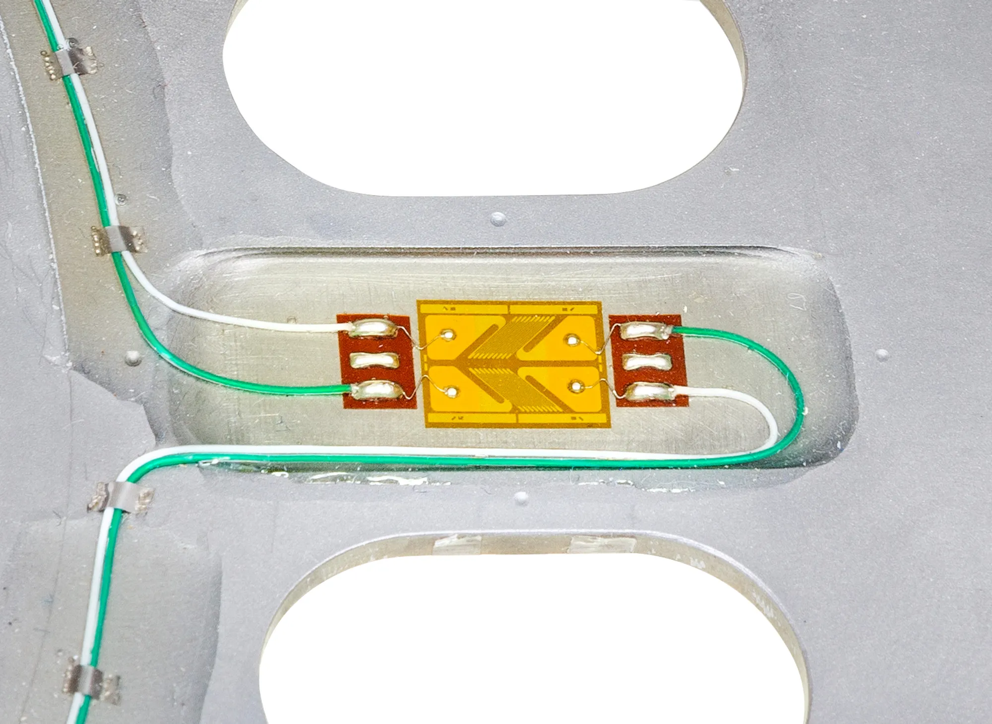
Michigan Scientific engineers use the solid model to place the gages for the measurements needed, and to work out where and how the instrumentation fits in the engine or on the dyno.
- 02
Apply the gages to the production shaft
Once the locations are fixed on the 3D model, the strain gages are applied to the production crankshaft at the Michigan Scientific facility.
Custom strain gage transducers - 03
Bring the signals out of the engine
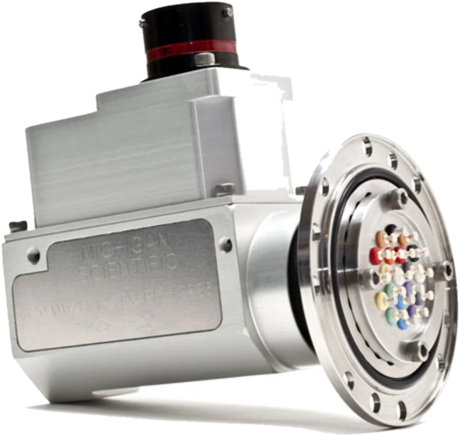
The signal wires are routed to a slip ring assembly or a wireless telemetry system. It is common to mount a slip ring and amplifier package on the engine damper.
Slip ring assemblies - 04
Record crank speed and position
An SR/ERT slip ring carries an encoder or a resolver that measures the angular speed, position and direction of rotation of the crankshaft. It uses none of the slip ring circuits, so all of them stay available for the strain channels.
SR/ERT Series slip rings
Torque, bending and strain in the fillets
Three kinds of measurement are common. The first is torque from the crank near the main journal bearing. The second is bending. The third is strain in highly stressed locations, such as the fillets of the throws.
The output torque at the flywheel end is usually the main measurement, and the other channels are correlated to it.
What the data is used for
Strain, torque, speed and position recorded together check the strength of the shaft and verify the simulations made during design. The torque into the transmission also serves the study of the drivetrain as a whole.
What you get
Your own crankshaft, returned as a transducer, with gages placed where your model says the measurement is needed. With a slip ring, torque and strain are recorded with crank speed and position, in the vehicle or on the dynamometer.
Frequent questions
Where is torque measured on a crankshaft?
Usually near the main journal bearing at the flywheel end. This is a direct measurement of the torque going into the transmission.
Can crank angle be recorded together with crankshaft strain?
Yes. An SR/ERT slip ring with an encoder or a resolver measures the angular speed and the position of the crankshaft alongside the strain channels, without using a slip ring circuit.
Is there a standard crankshaft torque transducer?
No. Engine types vary too much, so the production crankshaft is fitted with strain gages and becomes the transducer. Michigan Scientific has instrumented crankshafts from small motorcycle engines up to large 12-liter engines.
How do strain gage signals get out of a running engine?
The signal wires are routed to a slip ring assembly or a wireless telemetry system. It is common to mount a slip ring and amplifier package on the engine damper.
Similar applications
All applications-
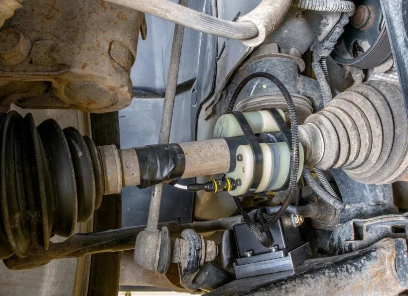 Powertrain Axle and half-shaft torque Drive torque measured on the production shaft, with a slip ring or telemetry to bring the signal out.
 -
 Temperature Temperature on rotating parts The temperature of a bearing, a compressor or a brake rotor, read while the part rotates under load.
 -
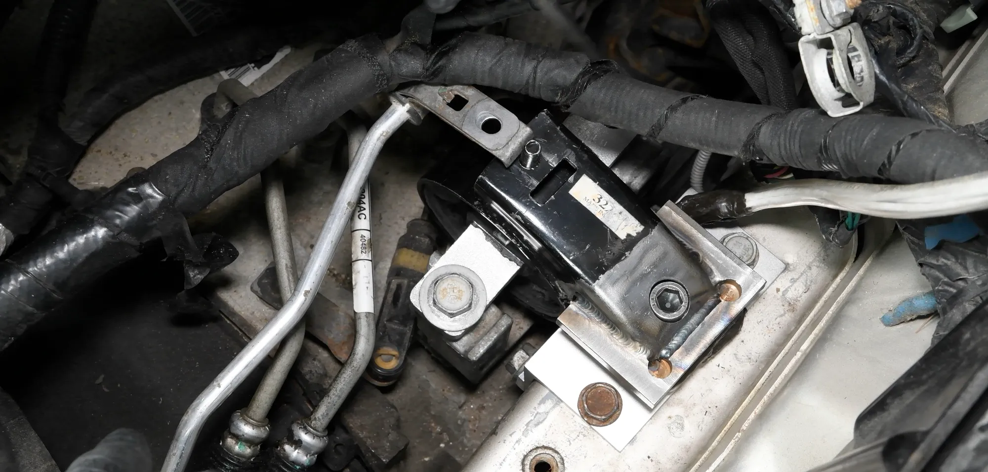 Component Engine mount loads The three forces each mount passes to the frame during start-up, acceleration and gear shifts.