
Application · Component
Measuring the three forces at an engine mount without moving the engine
In brief
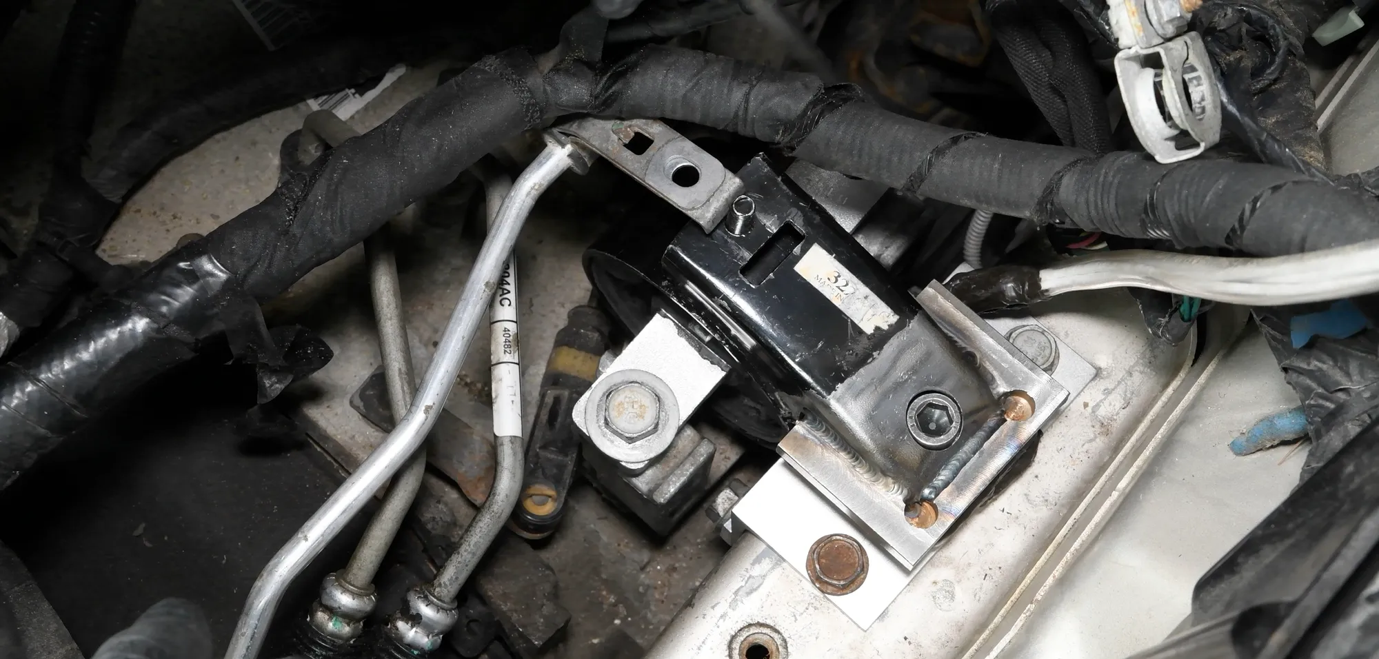
Engine mount forces are needed when a new vehicle is designed: they are the loads the powertrain passes to the frame. A TR3D three-axis load cell is placed in an adapter that replaces the production mount. The engine keeps its position and the rubber isolators stay in place. The data is used to design for chassis durability and to verify dynamic computer models.
- 17.8 kN
- capacity per axis of the TR3D-B-4K used in the van test
- 0.9 kN
- vertical force above engine weight in that test, over 200 lbf
- 1.1 to 444 kN
- capacity range of the TR3D series
Why measure forces at the mounts
The engine and the transmission are attached to the vehicle through their mounts. Every force the powertrain puts into the frame during engine start-up, acceleration or a hard maneuver goes through them. These forces are design loads for the mounts and the frame of a new vehicle.
In vehicle development, the measured forces are compared with the expected ones. Areas of the mount that see large forces repeatedly may need to be strengthened or redesigned.
Very little room under the hood
Modern engine compartments use nearly all the space available. Adding instrumentation at a mount is difficult without changing the position of the engine, and a test with the engine in another position or without its isolators no longer represents the production vehicle.
An adapter that replaces the production mount
The TR3D is a compact load cell that measures three perpendicular forces: longitudinal, lateral and vertical. It is built into an adapter that takes the place of the production mount and sends the reaction forces through the load cell. The engine and the surrounding components stay where they are, and the rubber isolators and other compliant parts are kept.

- 01
Start from the CAD data
Michigan Scientific application engineers take the CAD data of the vehicle components and design an adapter specific to that vehicle, in stainless steel or aluminum.
Custom transducers and adapters - 02
Keep bending out of the load cell
The adapter is designed to minimize the bending loads on the load cell and its crosstalk sensitivity, without interfering with the parts around it.
- 03
Make the adapter
It is made by modifying an existing part or machined from scratch in the Michigan Scientific machine shop.
- 04
Install it in place of the mount
The load cell is fitted in the adapter, and the adapter is installed on the engine in place of the original mount.
TR3D three-axis load cells
A van test: full acceleration from rest
In one test, a TR3D-B-4K with a capacity of 17.8 kN (4 000 lb) was installed in the engine mount adapter of a van. The static loads were zeroed before the run, so the output shows only the change in force during the test, without the weight of the engine.
The van started at rest and accelerated fully. Engine torque caused sharp changes in the vertical and lateral forces. The dips in the force trace mark the points where the transmission shifted gears. The mount saw about 0.9 kN (over 200 lbf) of vertical force on top of the static weight of the engine.
From passenger cars to Class 8 trucks
TR3D capacities run from 1.1 to 444 kN per axis, which covers mounts from light passenger cars to Class 8 trucks and agricultural equipment. The same method applies to transmission mounts. The measurement can be made on a test track or on a simulator.
What you get
The three forces at each instrumented mount, recorded with the powertrain in its production position. The data serves chassis durability design and the verification of dynamic computer models.
Frequent questions
Which forces are measured at an engine mount?
Three perpendicular forces: longitudinal, lateral and vertical. A TR3D three-axis load cell measures all three in one compact body.
Does a load cell at the engine mount change the position of the engine?
No. The load cell is built into an adapter that takes the place of the production mount. The engine stays in its position and the rubber isolators are kept.
What load cell capacity is used for an engine mount?
In a test on a van, a TR3D-B-4K with a capacity of 17.8 kN (4 000 lb) per axis was used. The TR3D series ranges from 1.1 to 444 kN, from light passenger cars to Class 8 trucks.
Can transmission mount forces be measured the same way?
Yes. The same method applies to transmission mounts, and the measurement can be made on a test track or on a simulator.
Similar applications
All applications-
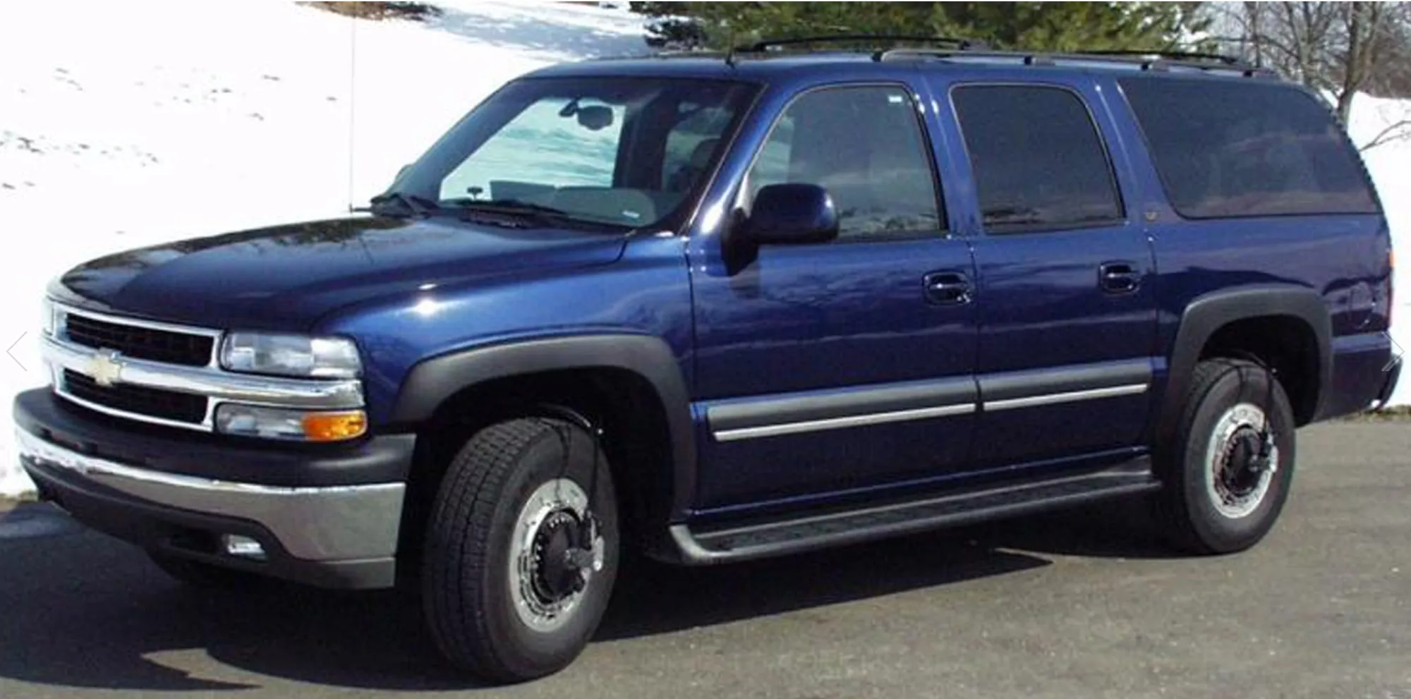 Suspension Suspension component loads How the wheel loads split between the suspension components and enter the chassis.
 -
 Durability Durability campaigns The load each wheel really sees on a pothole, an obstacle or a rough track, as recorded data.
 -
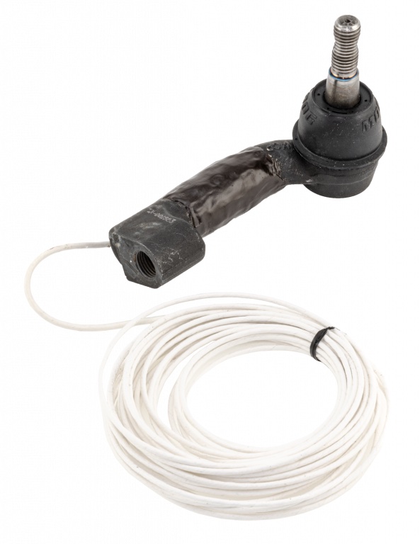 Steering Tie rod loads The tension and compression force in each tie rod while the vehicle is steered and driven.