
Application · Suspension
Measuring the forces in each suspension component, from tie rod to strut mount
In brief
A wheel force transducer gives the total force and moment at the wheel. To know how that load travels through the suspension and into the chassis, each component has to be measured. Michigan Scientific strain gages and calibrates the production parts where they can be gaged, and replaces a joint with a semi-custom transducer where they cannot. The data is used to correlate road load data acquisition with rig testing and for chassis durability work.
Why the load at the wheel is not enough
Designing and validating a suspension system requires the forces in its components. The total force and moment at the wheel can be measured with wheel force transducers, or estimated by virtual road methods.
That total does not say how the load is distributed. The same wheel load is shared between links, ball joints, the spring and the damper before it reaches the chassis. Only measurements on the components show the path.
Every part has its own shape and its own mounting
Not every component gives an accurate and meaningful force. Which one to instrument depends on the geometry of the component and on the layout of the suspension. The transducers also have to keep crosstalk low and stay insensitive to boundary conditions and mounting effects.
Struts are the hardest case. The coil spring and the damper work in parallel and are mounted directly to the chassis. Strain gages on the tube of a MacPherson strut do not give accurate results, because the piston moves inside the damper and the fluid pressure loads the tube.
The production part becomes the transducer
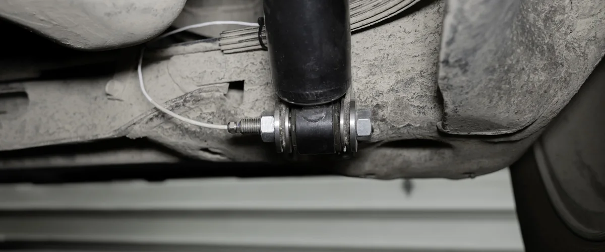
Wherever the geometry allows, the part the vehicle is built with is strain gaged and calibrated. Where it does not, a semi-custom transducer takes the place of a joint, such as a shear pin that replaces a bolt. Suspension height and geometry stay as they are.
- 01
Choose the components
The parts that will give the most accurate and meaningful forces are identified for your suspension layout. Michigan Scientific offers a free consultation for this work.
Custom strain gage transducers - 02
Place the gages
Complex parts go through FEA to find the strain gage type and location. This raises the output and reduces crosstalk.
- 03
Compensate and protect
Every transducer is temperature compensated and covered with a waterproof coating.
- 04
Calibrate as the part is mounted
Boundary conditions during calibration match those in the vehicle. On a fork or clevis, the bolt clamping load is made representative of the production installation.
Tie rods, ball joints, links and sway bars
Tie rods are commonly instrumented to measure steering forces. Either the inner or the outer tie rod can be gaged. The inner one is preferred, because it has more strain output and is generally more accurate. Suspension links and sway bar links are gaged for axial force, and the sway bar itself can be gaged and calibrated in torque.
Ball joints are instrumented to measure forces in two or three directions. The lower control arm ball joints often see the highest load. A reference line machined across the end of the stud marks the measurement axes, and a calibration fixture is made to match the ball joint geometry. At installation, the stud must not be bottomed out.
Struts and dampers: several ways in
Several methods measure the load in a strut or a damper without changing the suspension height or geometry. The choice follows the way the strut or damper is attached at the bottom, and what can be modified around it.
| Clamp-on strut transducer | Replaces the bottom bracket of a MacPherson strut and clamps onto the strut tube. Four-beam design in high strength stainless steel. No modification to the knuckle. |
|---|---|
| Shear pins at the knuckle | Replace the two bolts between the MacPherson strut and the knuckle. Minor modifications to the knuckle and the strut bracket. |
| Shear pin at the lower bushing | One or two axes, in place of the bolted joint at the bottom of the damper. Some modification to the damper bushing and the lower control arm. |
| Crossbar transducer | One or two axes, pressed into the bushing in place of the lower bolting crossbar. No modification to the lower control arm. |
| Gaged fork or clevis | The original part is strain gaged. The quickest and most cost-effective option when the geometry allows. |
| Gaged damper rod | Measures the force through the rod only. The shroud is removed or modified, and the rod end is sometimes drilled for the wire exit. |
| Damper top mount | Modified and gaged, or replaced by a custom transducer. Measures the total force from the damper to the chassis. |
Leaf springs, coil springs and strut mounts
On a rear suspension, the shackle can be instrumented to measure the vertical force from the leaf spring into the chassis at one end of the spring. FEA gives the gage location, and representative boundary conditions are critical for this transducer.
A coil spring can be gaged to measure the vertical load it carries, also in dynamic conditions. It can be calibrated in displacement as well, which relates spring compression to ride height and suspension travel.
On the body side, a three-axis load cell measures the forces at a strut mount. It gives the true vector force reacted by the vehicle body, without changing the position of the parts around it.
What you get
The force in each instrumented component, on the parts the vehicle is built with, in the conditions of the real test. Read with the wheel loads, the data shows how the load is distributed through the suspension and into the chassis. It supports the correlation between road data and rig tests, durability work and the simulations used to design the suspension and the chassis.
Frequent questions
Can strain gages on a MacPherson strut tube measure the strut force?
No. Strain gages on the tube of a MacPherson strut do not give accurate results, because the piston moves inside the damper and the fluid pressure loads the tube. A clamp-on strut transducer, or shear pins in place of the two bolts at the knuckle, are used instead.
How is damper force measured without changing the suspension geometry?
A shear pin or a crossbar transducer takes the place of the bolted joint at the bottom of the damper, or the fork, the damper rod or the top mount is strain gaged. These methods do not change the suspension height or geometry.
How are ball joint forces measured on a vehicle?
The ball joint is strain gaged to measure forces in two or three directions. A reference line machined across the end of the stud marks the measurement axes, and the calibration fixture is made to match the ball joint geometry.
How is the load carried by a coil spring measured?
The coil spring is strain gaged and calibrated for the vertical load it carries, also in dynamic conditions. It can also be calibrated in displacement, which relates spring compression to ride height and suspension travel.
Similar applications
All applications-
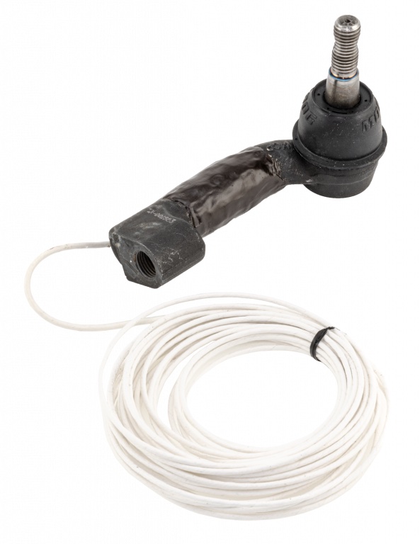 Steering Tie rod loads The tension and compression force in each tie rod while the vehicle is steered and driven.
 -
 Durability Wheel loads on the road Three forces and three moments at each wheel, recorded while the vehicle is driven.
 -
 Test rig Road simulators The loads measured at the wheel on the road, and the proof that the simulator reproduces them.