
Application · Suspension
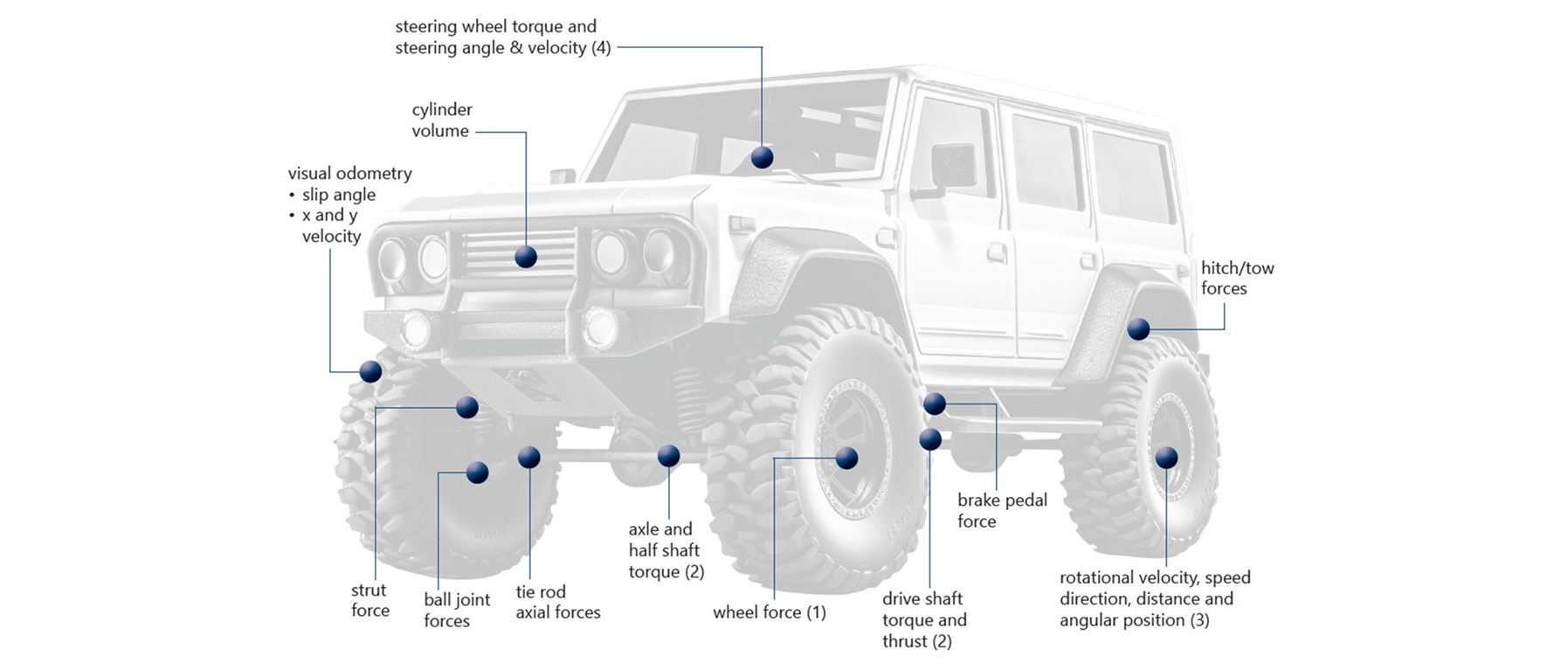
Measuring ball joint forces on the production part, with strain gages on the joint
In brief
Ball joint force is measured with strain gages applied to a standard ball joint from the vehicle suspension. The gaged joint measures the orthogonal forces: vertical, lateral and longitudinal. The strength of the production part is not reduced, so the load capacity of the transducer is the same as that of the standard part. Each transducer is temperature compensated, weatherproof and calibrated on a fixture made for its geometry.
- 2 or 3
- force directions measured in the ball joint
- Upper and lower
- ball joints made into transducers
- Unchanged
- load capacity of the production part
Why the ball joint is instrumented
The total force and moment at the wheel can be captured with wheel force transducers. To know how that load is distributed through the suspension and into the chassis, the components have to be measured one by one.
Most vehicles have several ball joints. The lower control arm ball joints often see the highest load and are the most important ones to instrument.
The measured forces describe the loads of normal usage. They are also used to benchmark current designs, to validate new designs and to validate FEA and CAE models.
The production ball joint becomes the transducer
Strain gages are applied to a standard ball joint from the vehicle suspension. The transducer measures the vertical, lateral and longitudinal forces in the joint. It can also be made for two directions only.
The ball joint keeps its normal configuration and operation, with only minor changes. The strength of the production part is not reduced, so the load capacities of the transducer are identical to those of the standard part.
Michigan Scientific makes these transducers from upper and lower ball joints. Every unit is weatherproof and temperature compensated, which limits the effect of temperature on the output during the test.
From the control arm to a calibrated ball joint
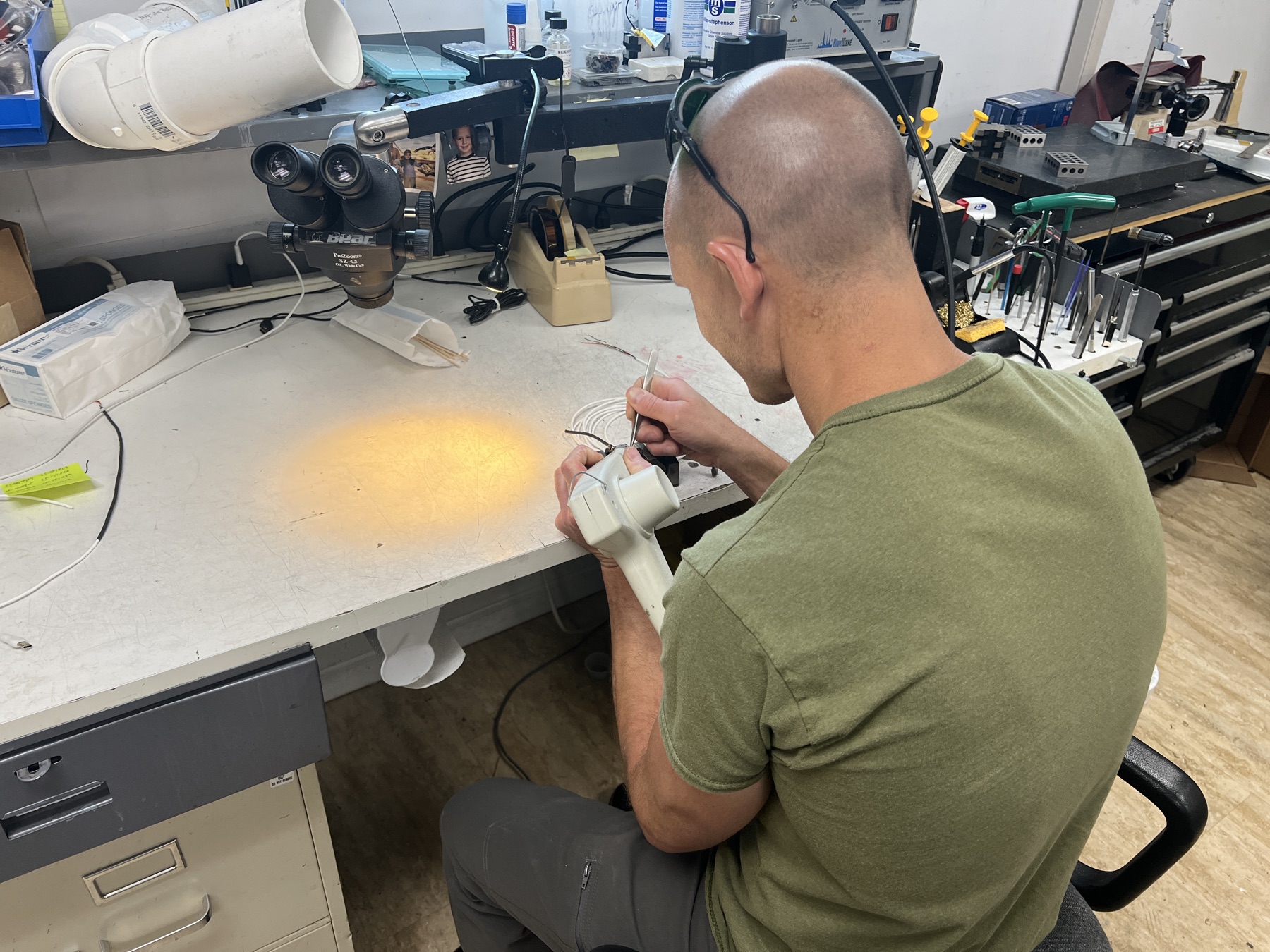
The ball joint is gaged out of the control arm when it can be removed, and in place when it cannot.
- 01
Remove the ball joint, or leave it in the arm
As an additional service, Michigan Scientific removes the ball joint from the control arm and reinstalls it afterward. If the design does not allow removal, the joint is strain gaged while still installed in the control arm.
Custom strain gage transducers - 02
Apply and protect the gages
The joint is strain gaged, temperature compensated and made weatherproof.
- 03
Mark the measurement axes
A reference line is machined across the end of the ball joint stud. It indicates the measurement axes.
- 04
Calibrate on a matching fixture
A custom calibration fixture is fabricated to match the geometry of the ball joint.
Calibration service - 05
Install without bottoming out the stud
To maintain the integrity of the transducer, care must be taken during installation to avoid bottoming out the ball joint stud.
Calibration of the gaged ball joint
Each gaged ball joint is calibrated on its own fixture, along the measurement axes marked by the reference line on the stud.
Michigan Scientific calibrates strain gage transducers from one to six axes in laboratories accredited to ISO/IEC 17025:2017, with reference equipment traceable to NIST. A transducer should come back for calibration after its first year of use, then at least every two years, and sooner if it took an impact or an overload.
Ball joint forces with the other suspension measurements
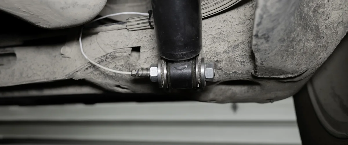
The other suspension components are instrumented in the same way. Tie rods are gaged for axial force, suspension links and sway bar links for axial force, and struts and dampers through transducers at their attachments.
With wheel force transducers on the same vehicle, the forces in the joints are read next to the total force and moment at the wheel. The measured loads are used to build and to verify the computer simulations of the chassis and the suspension.
What you get
The forces in the ball joint in two or three directions, measured on the production part with its strength and load capacity unchanged. The transducer is weatherproof and temperature compensated, for use on the vehicle, and it comes back calibrated on a fixture that matches its geometry.
Frequent questions
Does strain gaging a ball joint reduce its strength?
No. The strength of the production part is not reduced, so the load capacities of the ball joint transducer are identical to those of the standard part.
Can a ball joint be strain gaged without removing it from the control arm?
Yes. If the ball joint cannot be removed because of design constraints, strain gaging is performed with the joint still installed in the control arm.
Which ball joint should be instrumented first?
The lower control arm ball joint. It often experiences the highest load and is the most important one to instrument. Upper ball joints are made into transducers as well.
How are the measurement axes of a ball joint transducer identified?
By a reference line machined across the end of the ball joint stud. The line indicates the measurement axes when the joint is installed.
Similar applications
All applications-
 Suspension Suspension component loads How the wheel loads split between the suspension components and enter the chassis.
 -
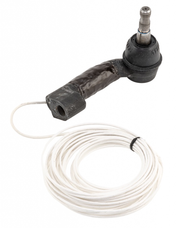 Steering Tie rod loads The tension and compression force in each tie rod while the vehicle is steered and driven.
 -
 Suspension MacPherson strut force The total load into a MacPherson strut, measured at its lower attachment or at its top mount.