
Application · Suspension
Measuring the force in a MacPherson strut without changing the suspension geometry
In brief
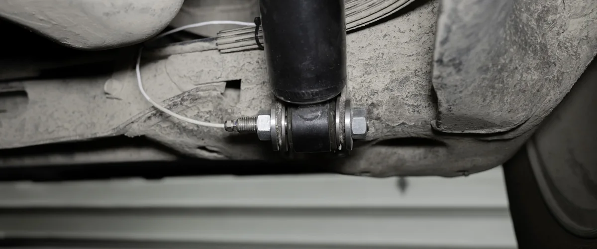
MacPherson strut force is measured on the vehicle at the lower attachment of the strut, not on its tube. A semi-custom transducer replaces the bottom bracket and clamps onto the strut tube, or two shear pins replace the bolts between the strut and the knuckle. Both capture the total load transmitted into the strut, and neither changes the suspension height or geometry. Strain gages on the strut tube do not give accurate results.
- 4 beams
- in the clamp-on strut transducer
- 2 bolts
- replaced by shear pins at the knuckle
- M12
- smallest bolt a shear pin has replaced
Why strut force is hard to measure
In a strut, the coil spring and the damper are arranged in parallel and mounted directly to the chassis. The force of interest is the total load that goes into the strut, and no single part of it carries that load alone.
Attempts have been made to put strain gages on the tube of a MacPherson strut. This method does not give accurate results, because the piston moves inside the damper and the fluid pressure acts inside the tube.
Two transducers for the joint between strut and knuckle
The first is a semi-custom transducer that replaces the bottom bracket portion of the strut and clamps onto the strut tube. It is a four-beam transducer made from high strength stainless steel. The knuckle is not modified.
The second replaces the two bolts that connect the strut to the knuckle with custom shear pins. The pins measure the load directly through the joint. This method needs minor modifications to the knuckle and to the strut bracket, and it preserves the suspension geometry.
| Clamp-on strut transducer | Replaces the bottom bracket and clamps onto the strut tube. Four beams, high strength stainless steel. No modification to the knuckle. |
|---|---|
| Shear pins at the knuckle | Replace the two bolts between the strut and the knuckle. Minor modifications to the knuckle and the strut bracket. |
From the strut layout to a calibrated transducer
The method follows the way the strut is attached at the bottom, and what may be modified around it. Michigan Scientific offers a free consultation and a quote for this work.
- 01
Describe the lower attachment
A bracket bolted to the knuckle, a through hole bushing, a bolting crossbar, or a fork or clevis. Each one has its own transducer.
Custom strain gage transducers - 02
Choose what may be modified
The clamp-on transducer leaves the knuckle as it is. Shear pins need minor modifications to the knuckle and the strut bracket.
- 03
Place the gages
Complex parts go through FEA to find the strain gage type and location. This raises the output and reduces crosstalk.
- 04
Compensate and protect
Every transducer is temperature compensated and covered with a waterproof coating.
Struts with a bushing, a crossbar or a fork at the bottom
Not every strut is bolted to the knuckle through a bracket. Each of the three other lower attachments takes its own transducer.
A shear pin transducer is a strain gage transducer that replaces a production bolt or pin and measures the forces perpendicular to it. Each one is designed for its application and machined from transducer grade stainless steel, with a weatherproof coating. Shear pins have replaced bolts as small as M12, and some have load ratings over 7 700 kg (17 000 lb).
| Lower through hole bushing | A one or two axis shear pin replaces the bolted joint at the bottom of the damper. Some modification to the damper bushing and the lower control arm. |
|---|---|
| Lower bolting crossbar | The crossbar is pressed or machined out and replaced by a one or two axis custom transducer. No modification to the lower control arm. |
| Lower fork or clevis | The original fork or clevis is strain gaged, with no replacement part. The quickest and least costly option when the geometry allows. |
Forces at the strut mount, on the body side
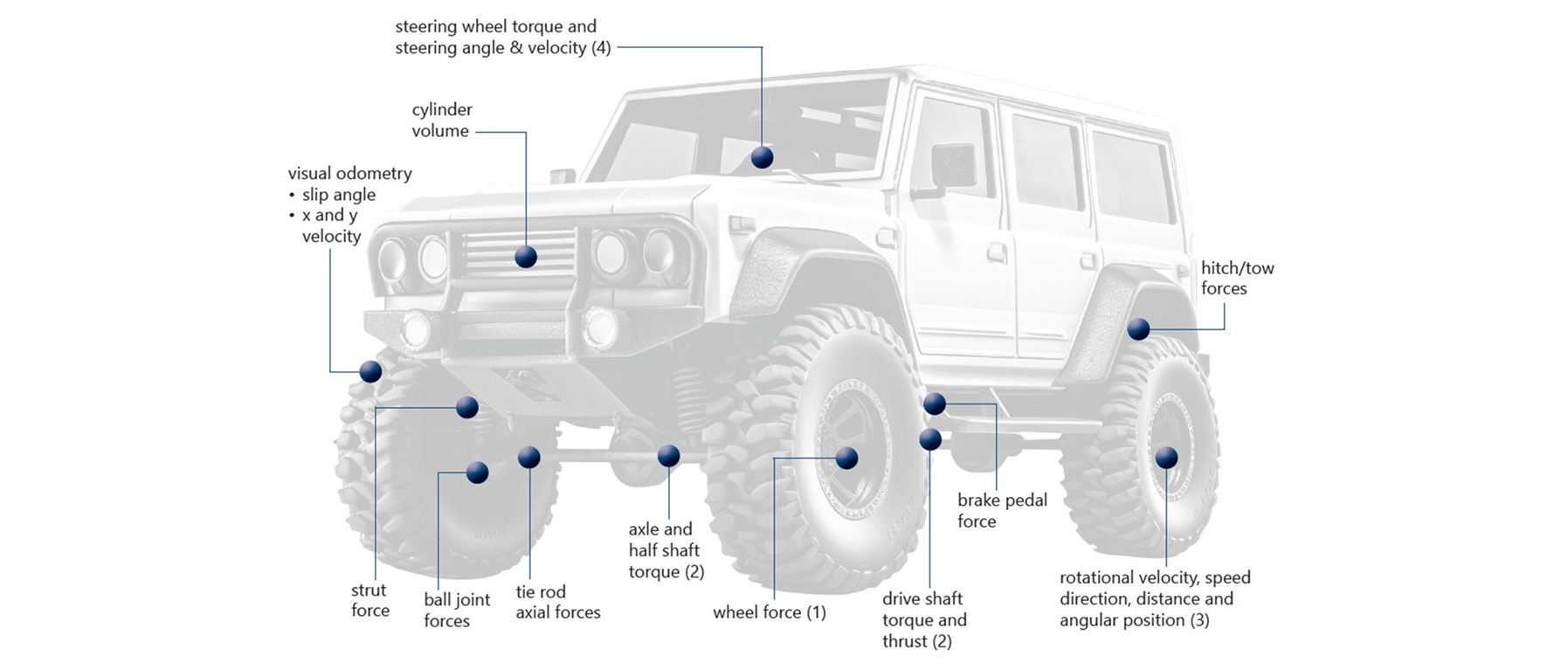
Three-axis load cells are used to measure strut mount forces. A three-axis load cell measures the forces in three perpendicular directions at the same time, in one compact body, and gives the true vector force reacted by the vehicle body.
The TR3D series covers 1.1 to 444 kN per axis. The compact bodies fit into an existing part after modification, or between purpose-made flanges.
What you get
The total load transmitted into the strut, measured at its lower attachment with the suspension height and geometry unchanged. A three-axis load cell at the strut mount adds the forces that the body reacts. Read with the wheel loads, the data shows how the load travels through the suspension and into the chassis.
Frequent questions
Why not put strain gages directly on the strut tube?
It does not give accurate results, because the piston moves inside the damper and the fluid pressure acts inside the tube. The force is measured at the lower attachment of the strut instead.
Which strut force transducer needs no modification to the knuckle?
The clamp-on strut transducer. It replaces the bottom bracket portion of the MacPherson strut and clamps onto the strut tube, so the knuckle is not modified.
Does measuring strut force change the ride height?
No. The clamp-on transducer and the shear pins at the knuckle measure the total load into the strut without altering the suspension height or geometry.
How is the force at the strut top mount measured?
With three-axis load cells. They measure three perpendicular forces at the mount and give the true vector force reacted by the vehicle body.
Similar applications
All applications-
 Suspension Suspension component loads How the wheel loads split between the suspension components and enter the chassis.
 -
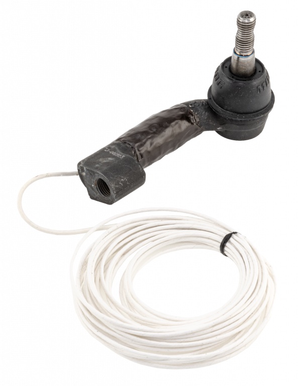 Steering Tie rod loads The tension and compression force in each tie rod while the vehicle is steered and driven.
 -
 Durability Wheel loads on the road Three forces and three moments at each wheel, recorded while the vehicle is driven.