Application · Rig
Measuring net forces and moments on a machine with four three-axis load cells
In brief
A single three-axis load cell measures three forces and has a limited moment rating. Four of them in an array, or between two plates, support larger forces and larger moments. Because the cells sit at different locations, their twelve outputs give the three net forces and the three net moments on the system. A junction box can also reduce the twelve signals to three force channels.
- 12
- strain gage bridge outputs from four three-axis load cells
- 15, 45 or 75 kN
- force capacity of the LP-3030, depending on the load cells fitted
- 3
- force channels at the output of the JB3 junction box
When one load cell is not enough
A three-axis load cell is compact, and it fits into a machine or a vehicle with adapters. It measures forces in three perpendicular directions. Some tests ask for more: a force above the capacity of the largest single cell, a large moment to support, or the moments themselves as a result.
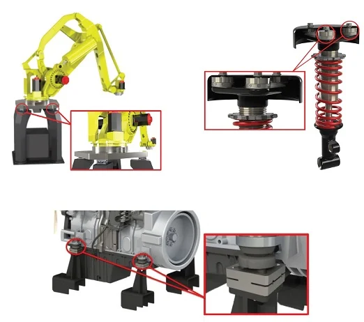
A typical case is the overhanging moment at the base of a robot arm in operation. A load platform, or load cell array, replaces the single cell there. It uses several three-axis load cells together, which raises the force and the moment ratings.
Each cell should see forces only
The array works if each load cell is fixed so that it sees forces only, and no local moment of its own. The platform or the mounting must be stiff enough for that. All the moments on the system are then reacted by the three forces measured at each cell.
The choice of cells depends on three things: load capacity, moment capacity and the space available. Standard TR3D models go from 1.1 kN to 444 kN (250 lb to 100,000 lb). Michigan Scientific engineers can also design the adapter plates and machine them in-house.
Four cells, twelve signals, six components
Each three-axis load cell has three independent outputs, so an array of four gives twelve channels. The forces are measured at each cell location. Combined, they give the net forces and the net moments acting on the system.
- 01
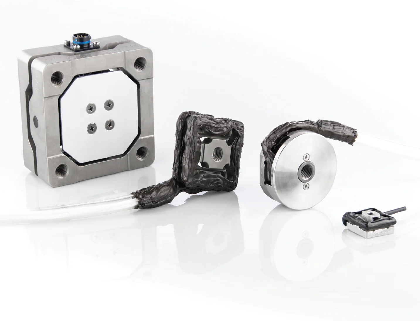
Choose four standard load cells
The model follows from the load capacity, the moment capacity and the size constraints of the test.
TR3D three-axis load cells - 02
Mount them to the equipment or to plates
The cells are bolted to the equipment or to custom mounting plates, so that each one is loaded in force only.
- 03
Condition the twelve bridges
When every channel is recorded, a twelve-channel amplifier box supplies 10 V bridge excitation to up to four three-axis load cells and gives ± 10 V per channel, with remote shunt calibration.
SGA12A amplifier box - 04
Calculate net forces and moments
Each net force is the sum of the four readings in its direction. Each net moment is a signed combination of the readings, times half the cell spacing, W/2 or L/2. The calculation is done in post-processing, or by a Michigan Scientific program for the SOMAT eDAQ system.
The LP-3030, a standard platform
The LP-3030 is the first standard load platform from Michigan Scientific. It is built with four TR3D-A load cells between an aluminum top plate and an aluminum bottom plate. The top plate has a grid of threaded holes for fixing the equipment under test.
Its force capacity is 15 kN, 45 kN or 75 kN, depending on the capacity of the load cells used. Like any array of four cells, it has twelve strain gage bridge outputs, which can all be recorded to calculate the net forces and moments.
Three channels instead of twelve with the JB3 junction box
The JB3 connects the signals of up to four three-axis load cells and outputs three force channels. The four Fx channels become one Fx output, and the same for Fy and Fz. No post-processing is needed for the net forces. For the net moments, the twelve channels are recorded.
Each input channel has a precision sensitivity trimming circuit that makes all load cell sensitivities equal. The output then stays the same wherever the load is applied on the platform.
| JB3-P | Passive. The load cells are combined in parallel, with no extra hardware. It connects to a three-channel strain gage module like a single three-axis load cell. |
|---|---|
| JB3-A | Amplified. Same components, plus strain gage amplifiers on the three outputs. It gives ± 10 V for any high-level voltage recorder. A PS-DC or PS-AC power supply powers the amplifiers and controls shunt calibration and bridge kill. |
What you get
The three net forces and the three net moments on the system, from standard three-axis load cells. With a JB3 junction box, the three net forces come out directly on three channels. The array carries larger forces and moments than a single cell.
Frequent questions
How many load cells does a force and moment platform use?
Four three-axis load cells. Each has three independent outputs, so the array gives twelve channels, and combining them gives the three net forces and the three net moments on the system.
Can the net forces be read without post-processing?
Yes. The JB3 junction box combines the signals of up to four three-axis load cells into three force channels, Fx, Fy and Fz. For the net moments, the twelve channels are recorded and the calculation is done afterwards.
What is the force capacity of the LP-3030 load platform?
15 kN, 45 kN or 75 kN, depending on the capacity of the load cells fitted. The LP-3030 is built with four TR3D-A load cells between two aluminum plates.
What is the difference between the JB3-P and the JB3-A junction boxes?
The JB3-P is passive: it combines the load cells in parallel and connects to a three-channel strain gage module like a single three-axis load cell. The JB3-A adds strain gage amplifiers on the three outputs and gives ± 10 V for a high-level voltage recorder.