
MUX-12 series signal conditioning
Twelve-channel quarter-bridge module: bridge completion, 4.5 V excitation and digitization onto one CAN 2.0 or CAN FD bus, up to 8 ksps, stackable to 48 channels.
Twelve analog channels onto one CAN 2.0 or CAN FD bus, up to 8 ksps: sensor excitation, conditioning and digitization in one module, stackable to 48 synchronized channels.
Model MUX-BC350-12
- 12
- Quarter-bridge channels
- 8 ksps
- Max output rate, CAN FD
- ± 5000 µε
- Strain range, max
- Ø 86 × 25.4 mm
- Housing
- 12
- Full-bridge channels
- 8 ksps
- Max output rate
- 12
- Thermocouple channels
- 1 ksps
- Max output rate
- K, J, T
- Thermocouple types
- 12
- High-level channels
- 8 ksps
- Max output rate
- 12
- PT100 RTD channels
- 8 ksps
- Max output rate
- OutputCAN 2.0 / CAN FD
- Max output rate8 ksps, CAN FD; 2 ksps, CAN 2.0
- StackingUp to 4 modules, 48 synchronized channels
- ConfigurationSoftware, per channel
Twelve quarter-bridge gages onto one CAN bus
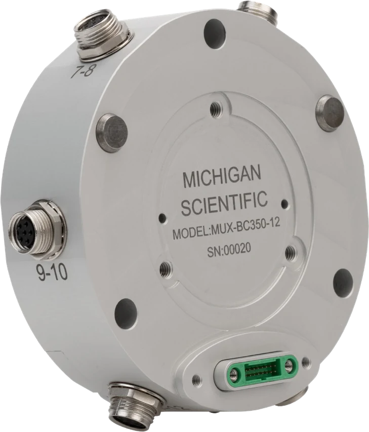
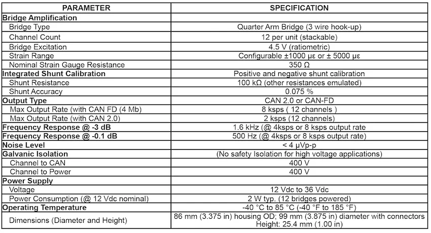
The MUX-BC350-12 takes twelve 350 Ω quarter-bridge strain gages in 3-wire hook-up, two per radial connector. It completes the bridges, excites them at 4.5 V ratiometric, amplifies and digitizes them, with a strain range configurable to ± 1000 or ± 5000 µε. Positive and negative shunt calibration uses an integrated 100 kΩ resistor, other values emulated, at 0.075 % accuracy. Output: CAN 2.0 at up to 2 ksps, CAN FD at 4 Mbit/s up to 8 ksps on 12 channels; 1.6 kHz at −3 dB, 500 Hz at −0.1 dB. Noise below 4 µVp-p. Galvanic isolation 400 V channel to CAN and channel to power, not a safety isolation for high-voltage applications. Supply 12 to 36 V DC, 2 W typical with 12 bridges powered; −40 to 85 °C; housing Ø 86 × 25.4 mm, Ø 99 mm over the connectors.
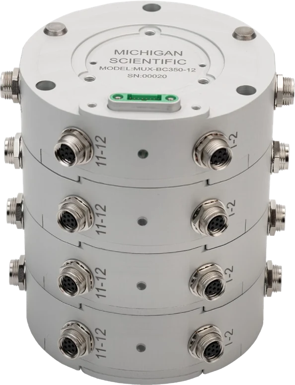
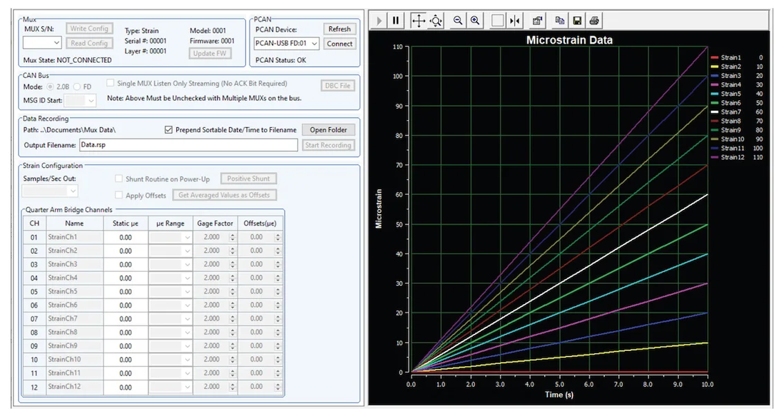
Four output connections, two for power, two for CAN. The supplied software configures each channel, gain included, triggers the shunt calibration, which can also run at power-up, records to a PC and generates the DBC file. Up to four modules stack for 48 synchronized channels on one power cable.
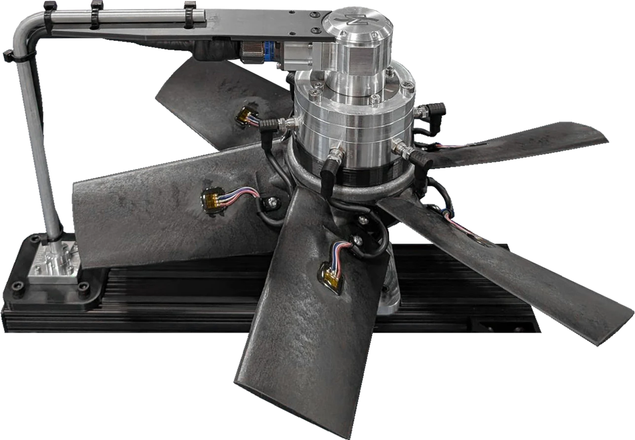
On a rotating part, the module pairs with any four-circuit Michigan Scientific slip ring, such as the S4, which then carries only power and CAN.
Twelve channels onto one CAN bus
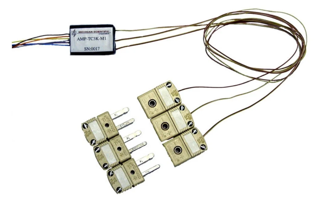
Five twelve-channel modules share one housing and one output: sensor excitation, conditioning and digitization, then CAN 2.0 at up to 2 ksps or CAN FD at up to 8 ksps. MUX-BC350-12: twelve 350 Ω quarter-arm strain gages, bridge completion included. MUX-FB-12: twelve full-bridge strain gage sensors. MUX-TC-12: twelve thermocouples, K, J or T, cold junction compensated and linearized, up to 1 ksps. MUX-HL-12: twelve high-level sensors, excitation provided for ratiometric sensors. MUX-RTD100-12: twelve PT100 RTDs.
Each channel is configured independently by software, gain included; shunt verification is integrated on the strain gage modules, and data records directly to a PC with the included software. Up to four modules stack for 48 synchronized channels. Inputs are galvanically isolated.
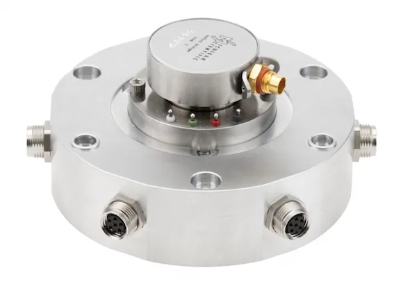
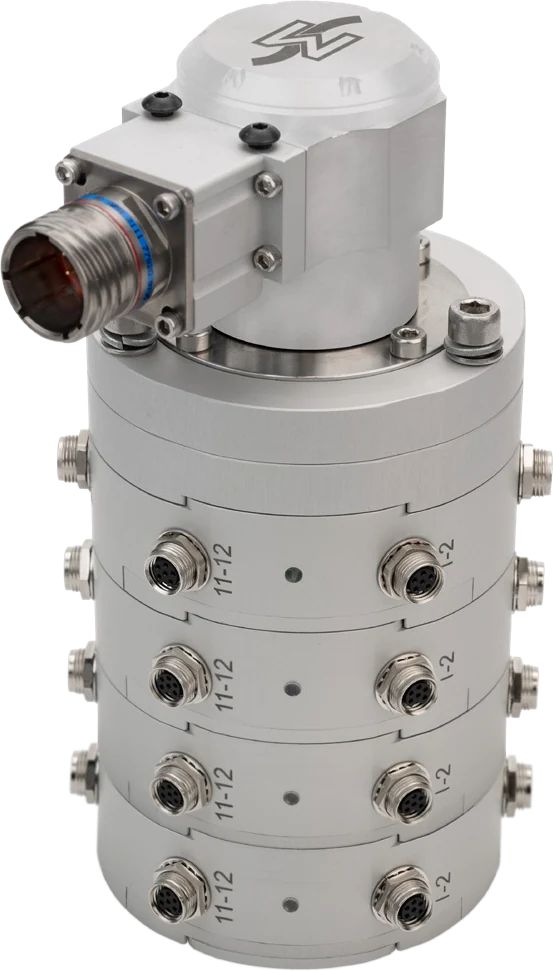
On a rotating part, a module pairs with any four-circuit Michigan Scientific slip ring. With the SR10AW/WFT slip ring, its 1024 ppr encoder is digitized and synchronized with the module data; the MUX-ENC-ADA mounting base joins slip ring and modules into one package.
Specifications
| Strain range | 5 000 µε (± 1000 or ± 5000 µε, configurable) |
|---|---|
| Channels | 12 (per module, stackable to 48 with four modules) |
| Input | Strain gage bridge (quarter bridge, 3-wire hook-up) |
| Output | CAN · CAN FD |
| Bandwidth | 1.6 kHz (−3 dB; 0.5 kHz at −0.1 dB, 4 or 8 ksps output rate) |
| Sample rate | 8 kHz (12 channels, CAN FD at 4 Mbit/s; 2 kHz on CAN 2.0) |
| Noise, referred to input | ≤ 4 µV (p-p) |
| Gain setting | Software (per channel; PC software included for configuration and data recording) |
| Shunt calibration | Positive · Negative · Software (integrated; also at power-up) |
| Shunt resistor | 100 kΩ (other values emulated) |
| Shunt accuracy | ≤ 0.075 % |
| Supply voltage | 12 to 36 V |
| Excitation voltage | 4.5 V (ratiometric) |
| Bridge resistance | 350 Ω |
| Power consumption | 2 W (typical, at 12 V DC with 12 bridges powered) |
| Bridge completion | Yes |
| Galvanic isolation | 400 V (channel to CAN and channel to power; not a safety isolation for high-voltage applications) |
| Dimensions | Ø 86 × 25.4 mm (housing; 99 mm diameter with connectors) |
| Operating temperature | −40 to 85 °C |
| Connections | Connector (inputs: 6 radial, two gages each; outputs: 4, two for power, two for CAN) |
| Channels | 12 (per module, stackable to 48 with four modules) |
|---|---|
| Input | Strain gage bridge (full bridge; integrated shunt resistors for sensor calibration) |
| Output | CAN · CAN FD |
| Sample rate | 8 kHz |
| Gain setting | Software (per channel; PC software included for configuration and data recording) |
| Channels | 12 (per module, stackable to 48 with four modules) |
|---|---|
| Input | Thermocouple |
| Thermocouple types | J · K · T |
| Output | CAN · CAN FD |
| Sample rate | 1 kHz |
| Gain setting | Software (per channel; PC software included for configuration and data recording) |
| Cold junction compensation | Yes (integrated, with linearization) |
| Channels | 12 (per module, stackable to 48 with four modules) |
|---|---|
| Input | Voltage (high level; sensor excitation provided for ratiometric sensors) |
| Output | CAN · CAN FD |
| Sample rate | 8 kHz |
| Gain setting | Software (per channel; PC software included for configuration and data recording) |
| Channels | 12 (per module, stackable to 48 with four modules) |
|---|---|
| Input | RTD (PT100, 100 Ω) |
| Output | CAN · CAN FD |
| Sample rate | 8 kHz |
| Gain setting | Software (per channel; PC software included for configuration and data recording) |
Request a quote
Resources
Datasheets and manuals
Drawings
None for this product.
CAD models
None for this product.
Guides and notes
A question on this product?
Describe the measurement. An application engineer answers.
More details to give? Use the full contact form.