
Application · Efficiency
Measuring torque and speed from the engine to the wheel to locate power losses

In brief
A loss can only be reduced once it is located. Torque and rotational speed are measured at the engine output, at the transmission output, at the axle and at the wheel, and the power going in and out of each stage maps the consumption. Production parts such as the flexplate, the driveshaft and the axle shafts are fitted with strain gages and become the transducers. At the wheel, a high-resolution torque transducer measures the small drag torques of the chassis on the road.
- About 1/3
- of engine power lost in the powertrain components
- 0.14 N·m
- resolution of the TW12.8HRMS175, cars and SUVs
- 1.5 N·m
- resolution of the TWHR2000, commercial trucks
Why the losses have to be located
Fuel economy regulations, such as the CAFE rules enacted in the United States in 1975 and similar rules in other countries, set efficiency targets that vehicles must meet by a given year. During development, manufacturers test to locate the powertrain losses that affect fuel economy.
A commonly accepted ratio is that about one third of the engine power is lost as heat, another third is lost in the powertrain components, and the last third propels the vehicle. The middle third can only be reduced once it is split between the components.
Power in and power out, stage by stage
The power going into and out of the engine components, the transmission and the driveline maps the power consumption. To get power, both torque and rotational speed must be measured. A wheel force transducer can give the overall output into the road.
Every one of these measurement points is on a rotating part inside the powertrain. The production component itself is strain gaged and becomes the transducer. A slip ring assembly or telemetry brings the signal out.
A torque measurement at each stage of the driveline
Transducers are installed in the development vehicle at each stage. Comparing the input and the output of a stage gives its efficiency directly.
- 01
Engine output
On an automatic transmission, strain gages are applied to the flexplate. On a manual, a torque transducer is installed on the flywheel. The crankshaft can also be gaged inside a deep bore, with the wires routed to a slip ring.
Crankshaft measurements - 02
Transmission output
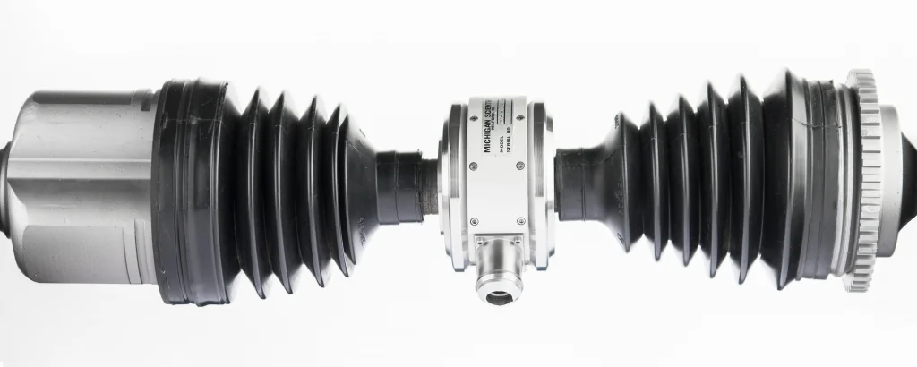
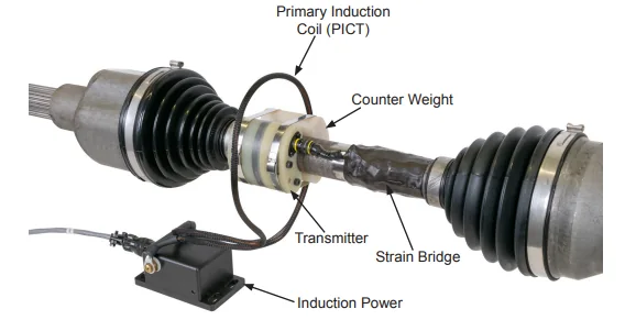
The transmission output shaft or the driveshafts are instrumented, with the wiring contained inside the shaft. The signal comes out through a slip ring at the front of the transmission, or by telemetry with induction or battery power.
Wireless telemetry systems - 03
Axle input and output
The driveshaft gives the input torque of the axle. The output is measured with gaged axle shafts or with wheel torque transducers. Comparing the two gives the axle efficiency.
Axle and half-shaft torque - 04
At the wheel
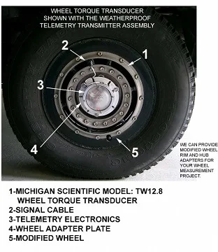
A wheel torque transducer measures the torque between the mounting hub and the tire.
TW series wheel torque transducers
Where a transmission loses power
With the flexplate giving the input power and the output shaft giving the output power, the overall efficiency of the transmission is measured directly. The main losses come from the torque converter, oil pumping and heat, viscous spin, and the gears, bearings and seals.
On the engine side, many components can be studied in the same way: cooling fans, friction between moving parts, oil and fuel pumps, belts, gears and lubrication.
Chassis losses: small torques measured on the road
Other losses sit outside the driveline. A high-resolution wheel torque transducer measures aerodynamic drag, brake drag, tire rolling drag and bearing seal drag in normal on-road driving. The TW12.8HRMS175, for cars and SUVs, resolves 0.14 N·m. The TWHR2000, for commercial trucks, resolves 1.5 N·m.
The transducer mounts on adapters that duplicate the critical dimensions of the production rim and hub, from passenger cars to class 8 trucks. Stainless steel and weatherproof sealing let it run in normal driving conditions. The same data is used in braking system, vehicle stability and driveline development.
What you get
The power entering and leaving each stage, from the engine output to the road, so that each loss has a location: transmission, axle or chassis. The design is then changed where the energy is lost.
Frequent questions
How is transmission efficiency measured on a vehicle?
The strain gaged flexplate gives the input power and the instrumented output shaft gives the output power. Comparing the two gives the overall efficiency of the transmission directly.
How are brake drag and tire rolling drag measured on the road?
With a high-resolution wheel torque transducer, which measures aerodynamic drag, brake drag, tire rolling drag and bearing seal drag in normal on-road driving. The TW12.8HRMS175 for cars and SUVs resolves 0.14 N·m, and the TWHR2000 for commercial trucks resolves 1.5 N·m.
How is engine output torque measured in the vehicle?
On an automatic transmission, strain gages are applied to the flexplate. On a manual transmission, a torque transducer is installed on the flywheel. The crankshaft can also be gaged inside a deep bore, with the wires routed to a slip ring.
How is axle efficiency measured?
The instrumented driveshaft gives the input torque of the axle, and the output is measured with gaged axle shafts or with wheel torque transducers. Comparing the two gives the axle efficiency.
Similar applications
All applications-
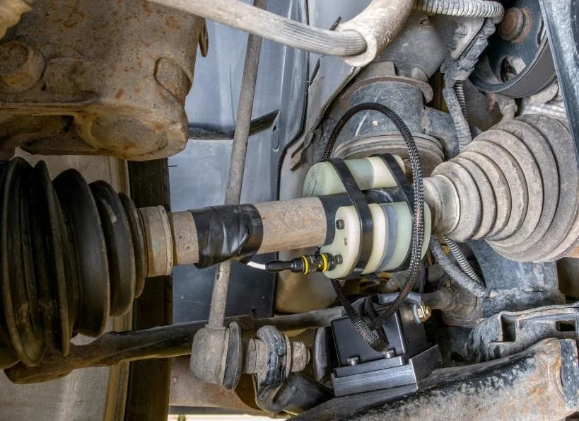 Powertrain Axle and half-shaft torque Drive torque measured on the production shaft, with a slip ring or telemetry to bring the signal out.
 -
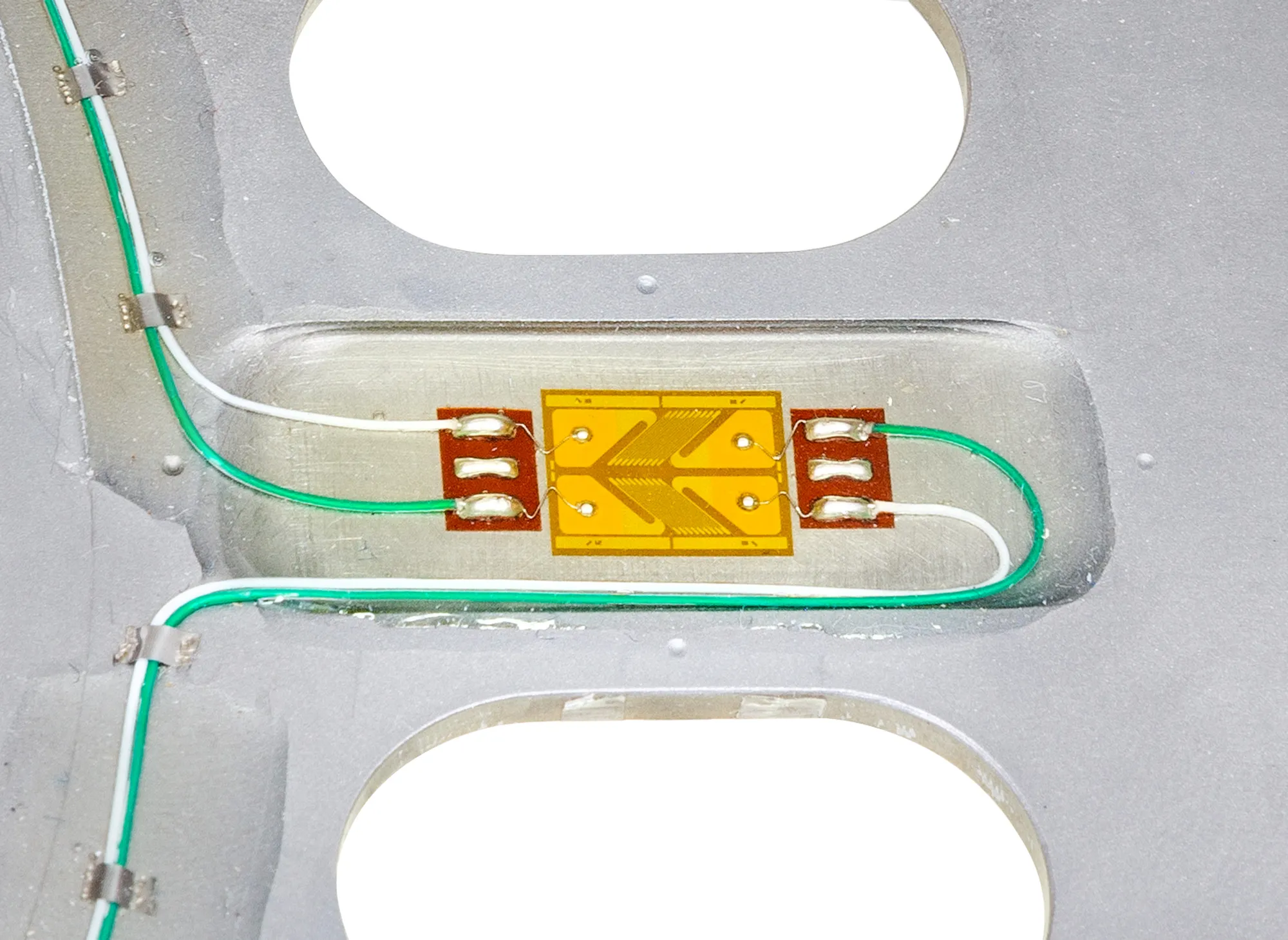 Engine Crankshaft measurements Torque, bending and strain on your own crankshaft with the engine running, in the vehicle or on the dyno.
 -
 Electric EV powertrain torque Torque at each stage of the electric drivetrain, from gearbox shafts to the wheel, to see where power is lost.