Application · Turbines
Measuring strain on the blades and in the gearbox of a wind turbine in operation
In brief
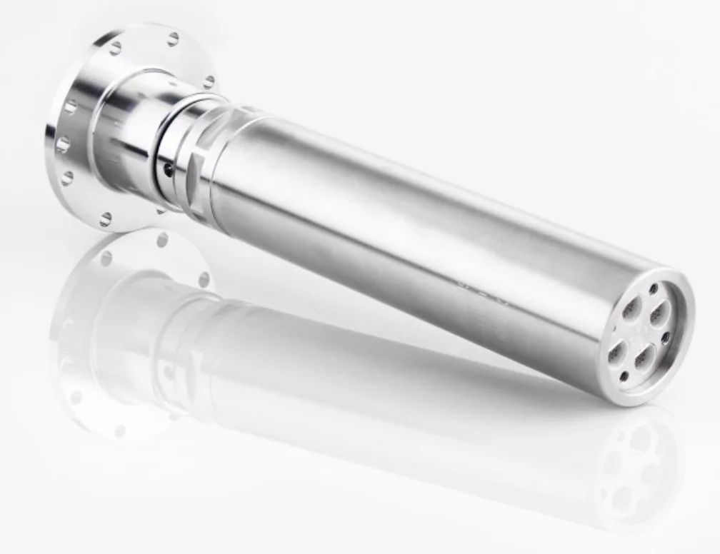
Strain on a wind turbine is measured with strain gages placed on the blades and in the gearbox, during operation. The gages turn with the rotor, so their signals leave it through a slip ring mounted on the end of the shaft. Michigan Scientific slip ring assemblies have often been used on wind turbines, both in the gearbox and on the blades. The SR45A-AXHS and SR60A-AXHS carry 45 or 60 circuits to a stationary data acquisition system.
- 45 or 60
- circuits on one end-of-shaft slip ring
- 250 mA
- maximum current per circuit
- 4 000 rpm
- maximum speed of the SR45A-AXHS and SR60A-AXHS
Where the strain gages go on a wind turbine
Strain gages go in the gearbox and on the blades: on several blades, or at many spots on one blade, to measure blade strain during operation.
The gages go at the areas of interest. The measurement is made with the turbine running, so every gage signal starts on a rotating part.
Many gages, all on the rotating side
The difficulty is the number of signals. Each strain gage needs its own connections, and a test that covers several blades soon asks for dozens of circuits between the rotor and the stationary recorder.
A strain gage signal is also a low-level signal. In the SR45A-AXHS and SR60A-AXHS, the brushes and rings are in wrought precious metals, with no plating. That keeps the variation of electrical resistance low enough for low-level instrumentation signals.
The wiring of the bridge matters too. With all four bridge arms on the spinning side, the rings are outside the bridge and cannot affect its balance.
From the gages to the recorder, in four steps
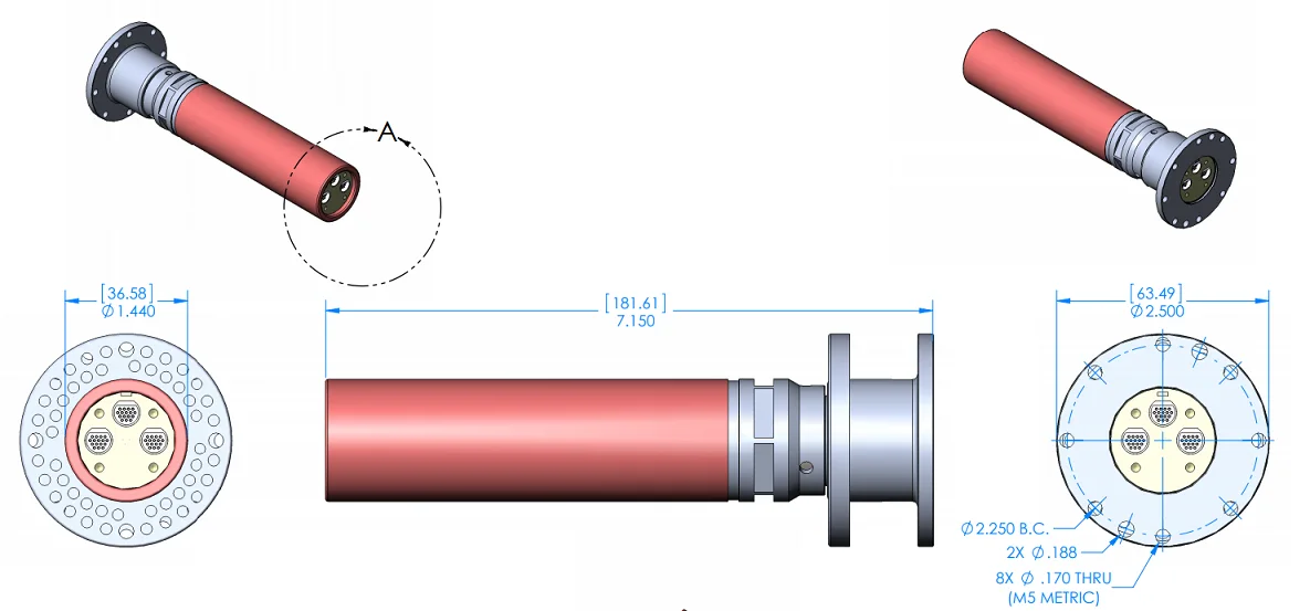
The slip ring mounts on the end of the rotating shaft. Its connections go through four circular connectors on the rotor and the stator.
- 01
Decide the gage layout
Gages go on several blades, or at many spots on one blade, and in the gearbox. The layout sets the number of circuits, and so the choice between 45 and 60.
- 02
Route the wires to the shaft end
The gage wires are brought to the rotor connectors of the slip ring, mounted on the end of the shaft.
SR45A-AXHS and SR60A-AXHS - 03
Keep the whole bridge on the rotor
Wire each bridge with its four arms on the spinning side. Peak ring noise then stays under 0.1 % of the data signal.
Strain gage circuits through a slip ring - 04
Record on the stationary side
The stator connectors go to the data acquisition system, which records all the strain channels together during operation.
What the 45 and 60 circuit slip rings are rated for
The two models differ in the number of circuits and in length. The bearings are lubricated for life and the assembly is sealed against dust, so no routine maintenance is needed.
| Circuits | 45 or 60 |
|---|---|
| Mounting | End of shaft |
| Maximum rotation speed | 4 000 rpm |
| Maximum current per circuit | 250 mA |
| Rotor diameter | 63.49 mm |
| Stator diameter | 36.58 mm |
| Length | 181.61 or 203.2 mm, depending on the model |
| Operating temperature | −40 to 121 °C |
| Connections | Circular connectors on rotor and stator |
Telemetry, the route with no contact
A telemetry system sends strain gage signals from a rotating part without contact. The transmitter is mounted on the rotating component and is powered by battery or by induction. Michigan Scientific describes this use for blade strain on jet turbines and for shafts in vehicle powertrains, and states that large applications can also use telemetry.
The Model T8 mounts on the end of a shaft and transmits eight strain gage channels. It is powered by induction and has no bearing and no wear parts. The receiver gives a ± 10 V analog output per channel.
What you get
The strain at many points on the blades and in the gearbox, recorded together while the turbine runs. A 45 or 60 circuit slip ring on the shaft end carries the gage circuits to the stationary recorder. Telemetry is the route with no contact, for up to eight channels per transmitter.
Frequent questions
How do strain gage signals leave a rotating wind turbine blade?
Through a slip ring mounted on the end of the shaft. The gage wires go to the rotor connectors, and the stator connectors go to a stationary data acquisition system. Michigan Scientific slip ring assemblies have often been used this way on wind turbines, on the blades and in the gearbox.
How many circuits does a slip ring for blade strain gages have?
The SR45A-AXHS has 45 circuits and the SR60A-AXHS has 60. Each circuit carries up to 250 mA, and the connections go through circular connectors on the rotor and the stator.
Does a slip ring add noise to a strain gage signal?
Very little when the bridge is wired correctly. With all four bridge arms on the spinning side, the rings are outside the bridge and peak ring noise stays under 0.1 % of the data signal.
Does a high channel count slip ring need maintenance?
No routine maintenance. The bearings of the SR45A-AXHS and SR60A-AXHS are lubricated for life and the assembly is sealed against dust.