
Application · Agriculture
Measuring torque, speed and temperature on the gearboxes of a combine harvester
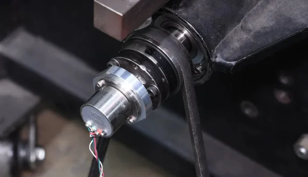
In brief
Gearbox torque on a combine harvester is measured on the machine's own parts. Pulleys and gears, including the gear teeth, are fitted with strain gages, and a slip ring or a telemetry transmitter carries the signal from the rotating part to the recorder. Speed and temperature are measured with the torque. Together they give the share of power that each system takes, which is how significant power losses are found.
- 4 to 10
- circuits on an S-Series end-of-shaft slip ring
- 12 000 rpm
- standard maximum speed of the S-Series
- 25 mm
- smallest shaft diameter for clamp-on telemetry
Why power is measured system by system
The power distribution of a farm machine is the basis for improving its fuel efficiency and productivity. Speed, torque and temperature can be measured on nearly every system of the machine. Torque and speed give the power that goes to each system, which locates the significant losses.
The work applies to diesel and to electric machines. On an electric machine, battery capacity is a major constraint, so the efficiency of every system has to be understood. The tests cover normal field operations as well as set test conditions.
The torque is inside the machine, on parts that turn
The torque to measure is on pulleys and gears, and these parts rotate. The signal has to reach a recorder that does not. No catalog transducer fits inside a gearbox or in place of a pulley.
The component itself therefore becomes the transducer. Michigan Scientific gages stock components, and the instrumentation is designed to change the strength and the other characteristics of the part as little as possible.
Instrumenting a pulley, a gear or a gearbox
Michigan Scientific instruments pulleys and gears, including the gear teeth, to measure the speed, the torque and the temperature they see in use. Past agricultural work includes gages applied inside a gearbox and pulley or gear transducers made from customer components.
- 01
Gage the component
Strain gages are applied to the pulley, the gear or the shaft of the gearbox, on the customer's own part.
Strain gauge services - 02
Bring the signal out through a slip ring
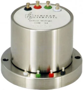
A slip ring transfers the data from the part to the data acquisition system. The S-Series mounts on the end of the shaft with two screws and connects strain gages and thermocouples through 4, 6, 8 or 10 circuits.
S-Series end-of-shaft slip rings - 03
Or use telemetry, or a tubular slip ring
Where the shaft end is not free, the torque signal is carried by a telemetry system or by a tubular slip ring that slides over the shaft. Clamp-on transmitters fit shafts from 25 mm in diameter.
Wireless telemetry systems - 04
Record torque, speed and temperature together
The three quantities are recorded during long-term tests in general use and in set test conditions. They give the power that goes through the part.
An example: the elbow gearbox of the unloading auger
The unloading auger transfers the harvested crop into a truck or a cart. The auger moves into position over the transfer point, then gears power it to move the crop through the auger tube. The elbow gearbox transmits that drive.
The speed, the torque and the temperature of the elbow gearbox are measured together. The data is used to improve its durability and efficiency.
Forces on rotor blades and feeder slats
Torque is not the only load. Forces on moving components inside an assembly are measured with multi-axis load cells or with strain gages applied to the part. Multi-axis load cells can be mounted to rotor blades, and feeder slats can be instrumented with custom gaging.
A telemetry transmitter sends the data from the load cell to the recorder without wires. The TR3D measures three perpendicular forces in one body, from 1.1 to 444 kN, and is built for endurance tests in the field and on the bench.
What you get
Torque, speed and temperature on the pulleys, gears and gearboxes of the combine, measured on its own parts in the field. The data shows how power is distributed between the systems and where it is lost.
Frequent questions
How is torque measured on a combine pulley or gear?
The pulley or the gear itself is fitted with strain gages, including on the gear teeth. A slip ring transfers the signal from the rotating part to the data acquisition system.
How are power losses found in farm equipment?
By measuring speed, torque and temperature on each system of the machine. Torque and speed give the power that goes to each system, which shows where the significant losses are.
How does the signal leave a gear that turns inside a gearbox?
Through a slip ring, or by telemetry. An end-of-shaft slip ring such as the S-Series mounts on the shaft end and carries 4 to 10 circuits. A telemetry system or a tubular slip ring is used on the shaft itself.
Do these measurements apply to electric farm machines?
Yes. Power distribution is measured on diesel and on electric farm equipment. On an electric machine, battery capacity is a major constraint, so the efficiency of every system has to be known.
Similar applications
All applications-
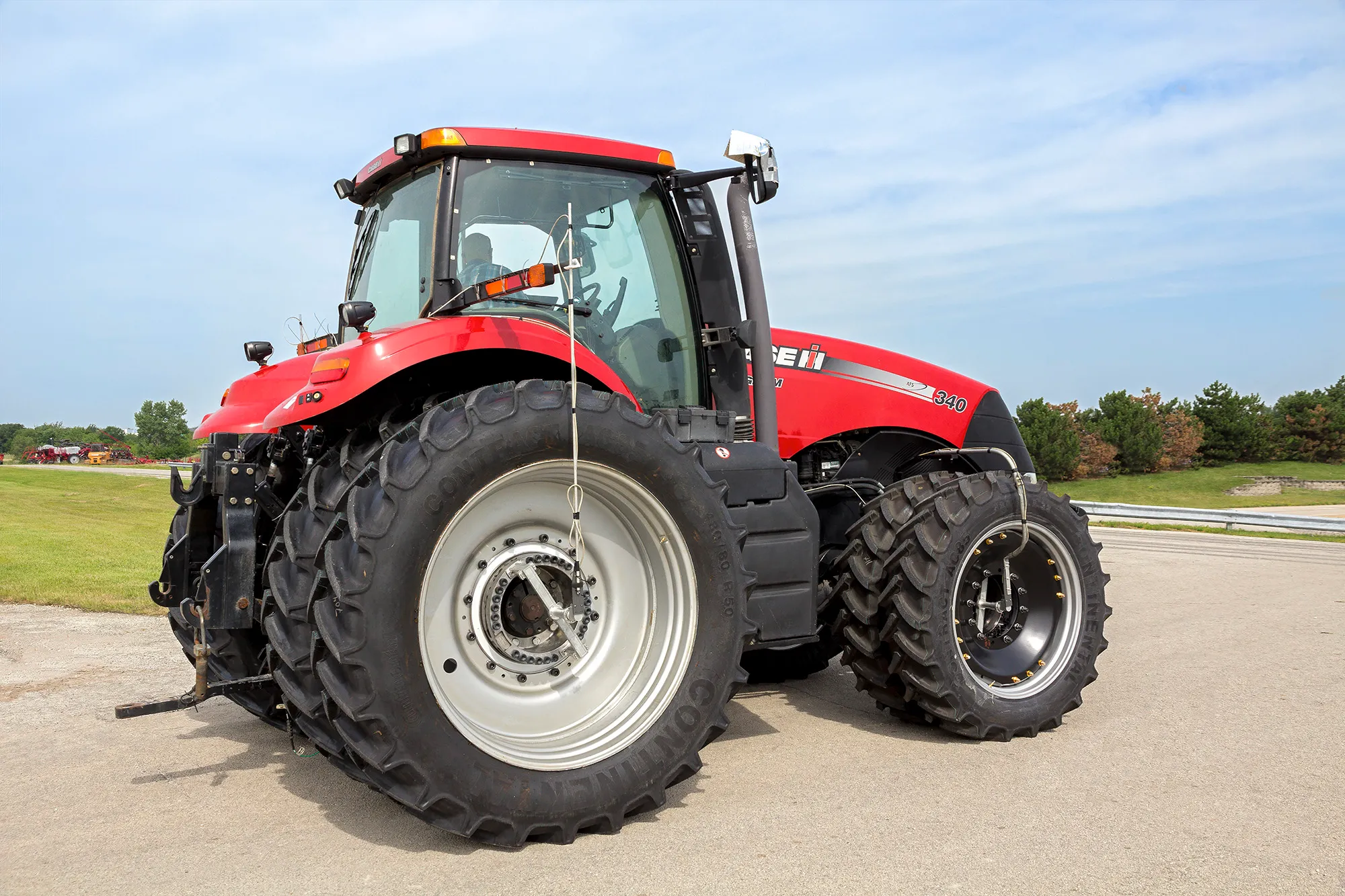 Agriculture Agricultural machinery Wheel loads, wheel torque, PTO power and forces on working parts, measured on the machine at work.
 -
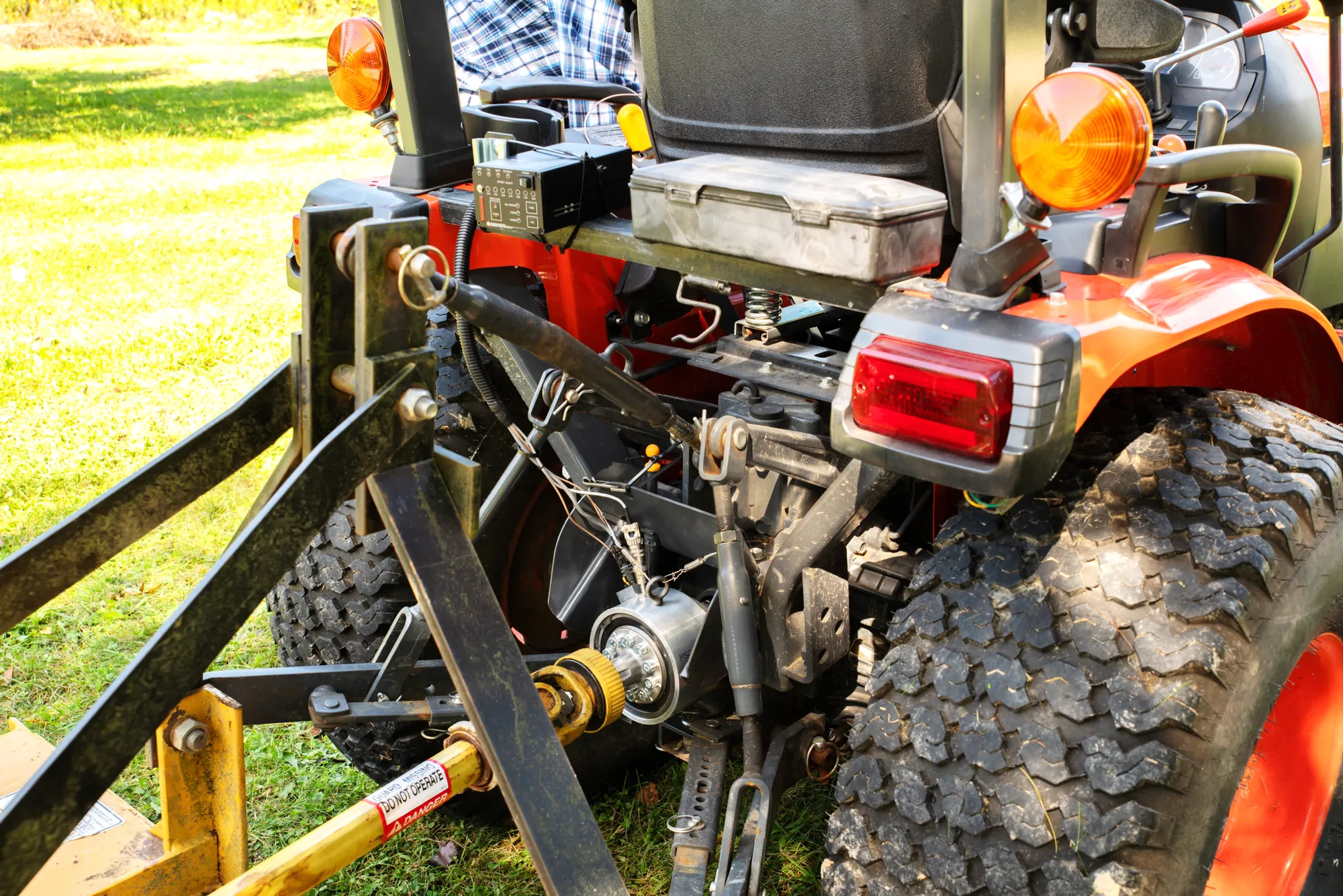 Agriculture PTO torque and power The torque and speed that the tractor delivers to the implement, measured during real field work.
 -
 Efficiency Vehicle efficiency and power mapping Torque and speed measured at each driveline stage, from engine to wheel, so each power loss has a location.