
Recording three forces and three moments at each wheel while the vehicle is driven
In brief
Everything the road puts into a vehicle goes through the wheel center. A wheel force transducer takes the place of the wheel center, between a hub adapter and a rim adapter made for the vehicle, and measures the three forces and the three moments there while the vehicle is driven on the real surface. The signals are amplified and digitized on the wheel, leave it through a slip ring or a telemetry package, and the CT2 interface box expresses them in vehicle axes in real time. The road load data is recorded on proving ground surfaces and over single events such as a pothole.
- 6
- load components measured at the wheel center
- 15.5 to 700 kN
- radial force capacity, LW series
- ISO/IEC 17025
- calibration, with a matrix and a certificate per serial number
Load path
The transducer is a stainless steel ring between the rim adapter and the hub adapter. Under load the ring deforms, and four-arm strain gage bridges turn that strain into one signal per component. The measurement is made on a rotating part: the forces turn with the wheel, so the signals are expressed in the axes of the vehicle with the wheel angle at every instant.
The six components act at the same time, and a load in one direction appears in part in the signal of another. Each transducer ships with its calibration matrix, which corrects this crosstalk; the cross-axis sensitivity after correction is below 0.5 % of full scale on the LW12.8-50. The transducer also works next to the brake and in the weather: it is temperature compensated and weatherproof.
Instrumentation
The LW series covers vehicles from a motorcycle to a class 8 truck. The capacity given is the radial force, Fx and Fz. The same transducer also mounts on a test rig through flanges or hubs, spinning or not.
| Motorcycle | LW-MC-3.5K, 15.5 kN |
|---|---|
| Passenger car and SUV | LW12.8-50, 50 kN · LW65, 65 kN |
| Heavy SUV and pick-up truck | LW-2T-20K, 90 kN |
| Medium duty vehicle | LW-2T-30K, 133 kN |
| Class 8 trucks and tractors | LW-2T-100K-S, 445 kN |
| Very heavy vehicles | LW700, 700 kN, hubs with a 425 mm bolt circle |
| Also measured | wheel angle at 0.17° resolution with the slip ring, wheel speed, X and Z acceleration |
| Environment | weatherproof, temperature compensated, −40 to 125 °C |
Signal path
A wheel force measurement has three parts: the transducer, the link that takes the signals off the wheel, and the interface box in the cabin. The amplifier mounted on the transducer digitizes the bridge signals. They leave the wheel through a slip ring, which also carries the encoder for wheel angle and speed, or through a telemetry transmitter powered by induction; the two packages are swappable on the same transducer. The CT2 interface box uses the wheel angle to do the coordinate transformation and corrects the crosstalk, in real time, and gives analog, CAN and Ethernet outputs to the recorder.
Procedure
- 01
Replace the wheel center
The transducer is bolted between a rim adapter and a hub adapter made for the wheel. The adapters keep the original offset: a wider track would change the loads being measured.
LW series wheel force transducers - 02
Hold the stator
The slip ring stator rod is held vertical from the body on non-steered wheels. On steered wheels, the stator angle correction device corrects the wheel angle in real time.
Stator restraint and angle correction - 03
Shunt calibration and zero
Power the interface boxes, run the shunt calibration, then zero with the vehicle on a hoist while each wheel turns two revolutions. Use the calibration delivered with that transducer serial number.
- 04
Three checks on the track
Static weight on Fz, a coast-down on Fx, a slow circle on Fy. They check the sign and the order of magnitude of each force on each wheel before the test.
- 05
Watch the brake heat
Long descents heat the hub. The transducer is temperature compensated, but the zero is checked before and after each run and the transducer temperature is logged.
Pothole at 40 km/h
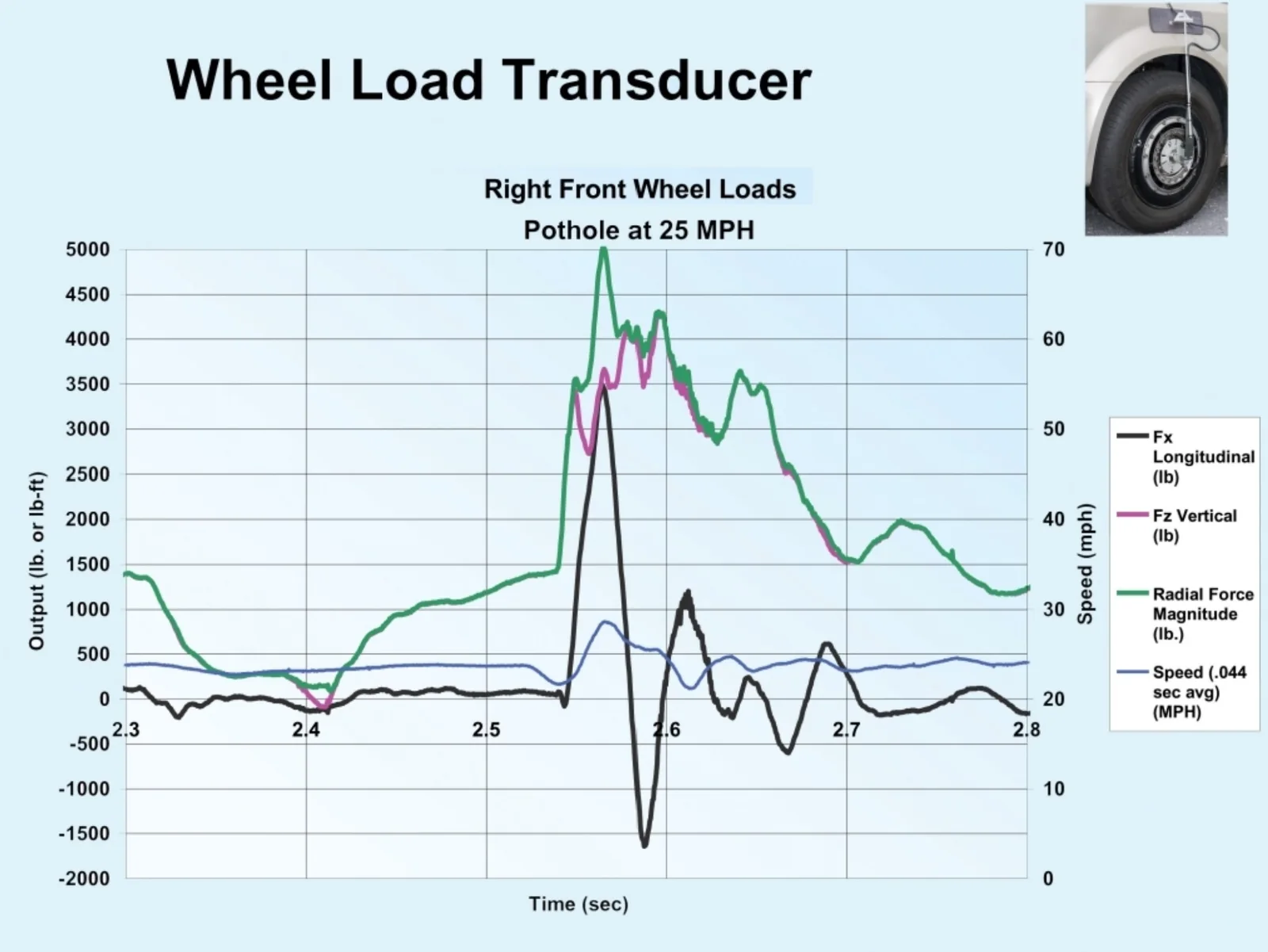
Road load data is recorded on proving ground surfaces and over single events. In this recording, the right front wheel of an SUV hits a pothole at 40 km/h (25 mph). The vertical force drops at the pothole entrance, then spikes as the suspension compresses at the bottom; the longitudinal force spikes when the wheel hits the edge. The loads are recorded with the wheel speed, so each peak is related to the event that caused it.
Result
The six load components at each wheel, in vehicle axes, with wheel speed and angle, recorded on the real vehicle and the real surface. The data is the road load input for durability work and for the test rig.
Frequent questions
What does a wheel force transducer measure?
The three forces and the three moments at the wheel center while the vehicle is driven, with the wheel angle, the wheel speed and the X and Z acceleration.
Which wheel force transducer capacity fits a passenger car?
The LW12.8-50, 50 kN radial, or the LW65, 65 kN. The series runs from 15.5 kN for a motorcycle to 445 kN for class 8 trucks and tractors, and 700 kN on the LW700.
Should a wheel force transducer use a slip ring or telemetry?
The slip ring is the default; it is wired and carries the encoder. Telemetry leaves no cable through the hub. The two packages are swappable on the same transducer.
How do you check a wheel force transducer installation before a test?
Shunt calibration, zero on the hoist with two wheel revolutions, then three checks on the track: static weight on Fz, a coast-down on Fx and a slow circle on Fy.
Similar applications
All applications-
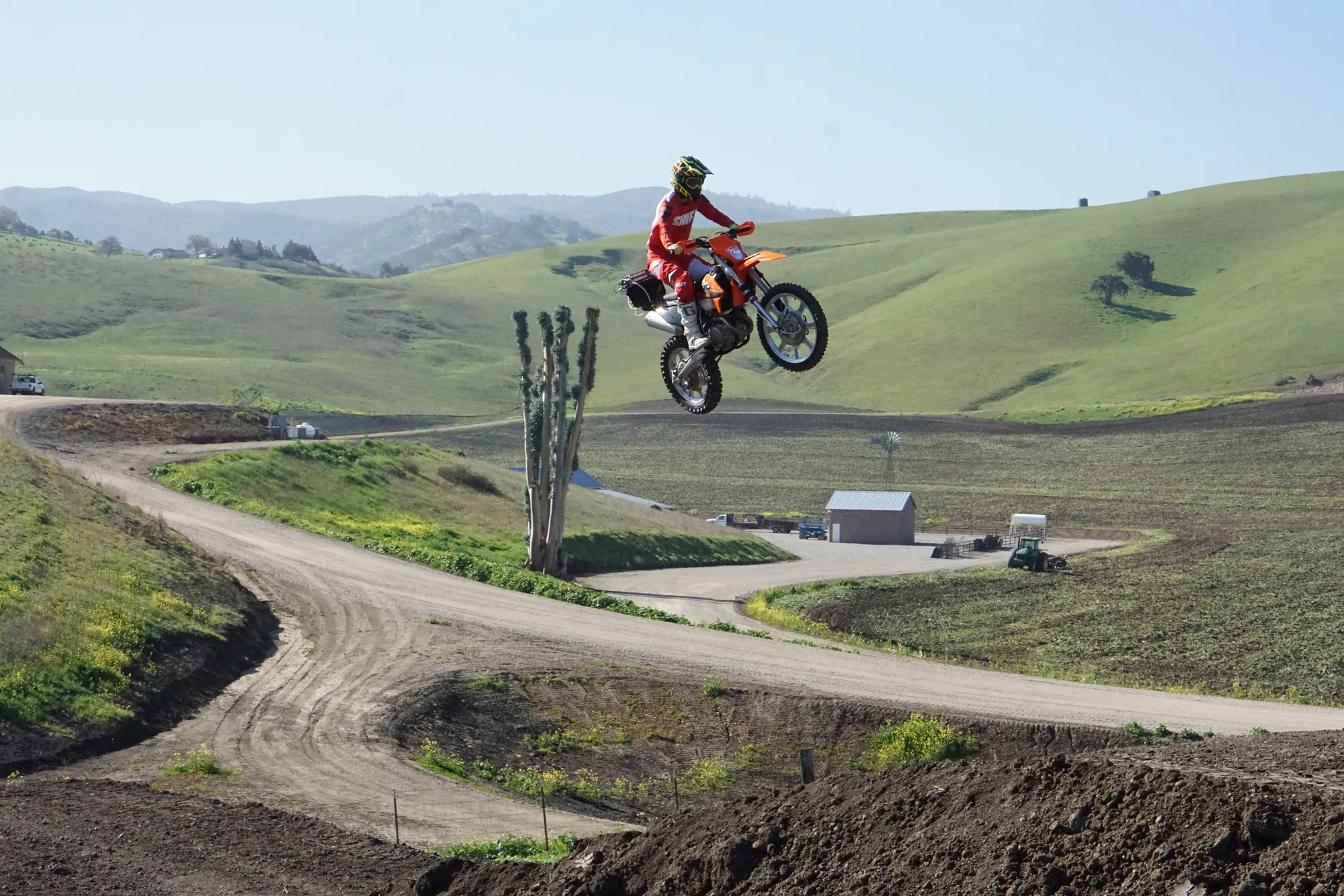 Durability Durability campaigns The load each wheel really sees on a pothole, an obstacle or a rough track, as recorded data.
-
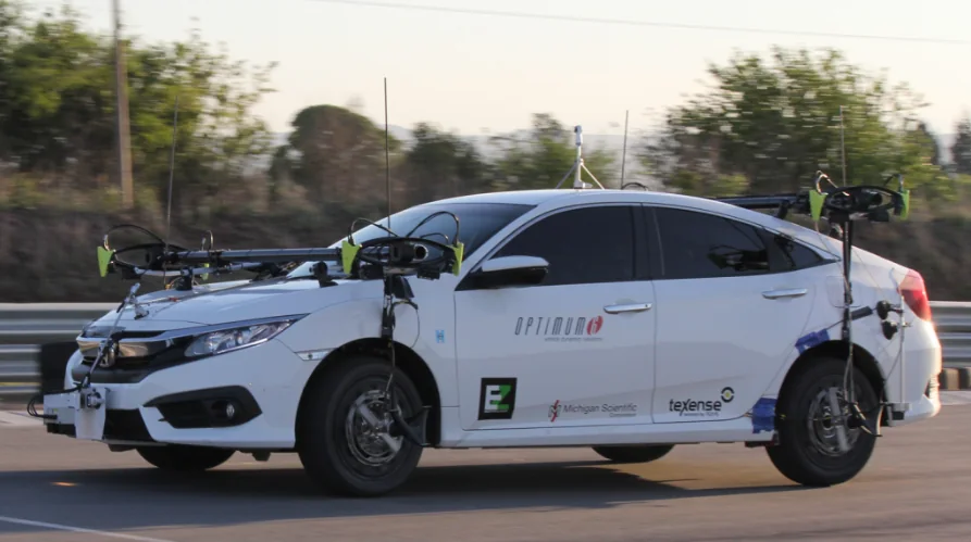 Dynamics Vehicle dynamics The forces and moments at each wheel while the vehicle brakes, turns and changes lane.
-
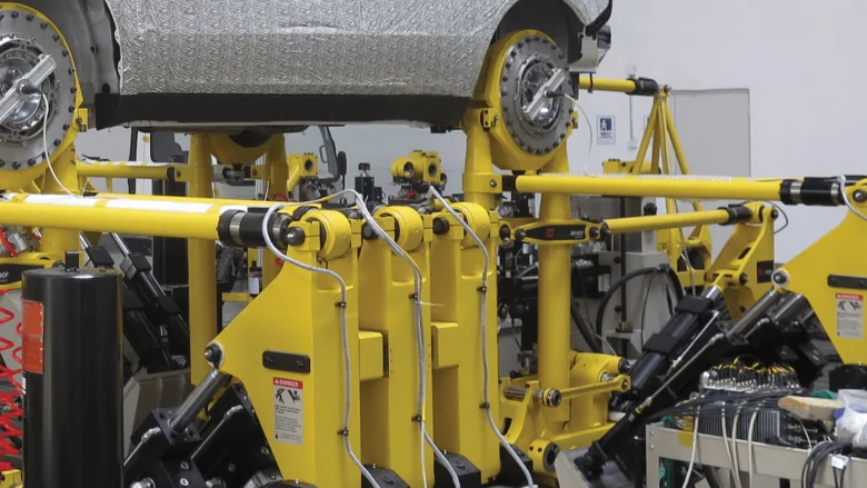 Test rig Road simulators The loads measured at the wheel on the road, and the proof that the simulator reproduces them.