
Application · Crash
Measuring the force of an impact on a crash barrier with a wall of load cells
In brief
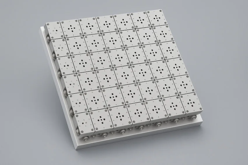
The force on a crash barrier is measured with three-axis load cells assembled side by side into an impact measuring panel. Each cell measures the force it receives in three directions. The CT500 is made for this test: its natural frequency is above 1 800 Hz, its face is a standard 124 × 124 mm, and its range is ± 500 kN on X, the impact axis, and ± 125 kN on Y and Z.
- ± 500 kN
- measuring range on X (impact axis), per cell
- ± 125 kN
- measuring range on Y and Z, per cell
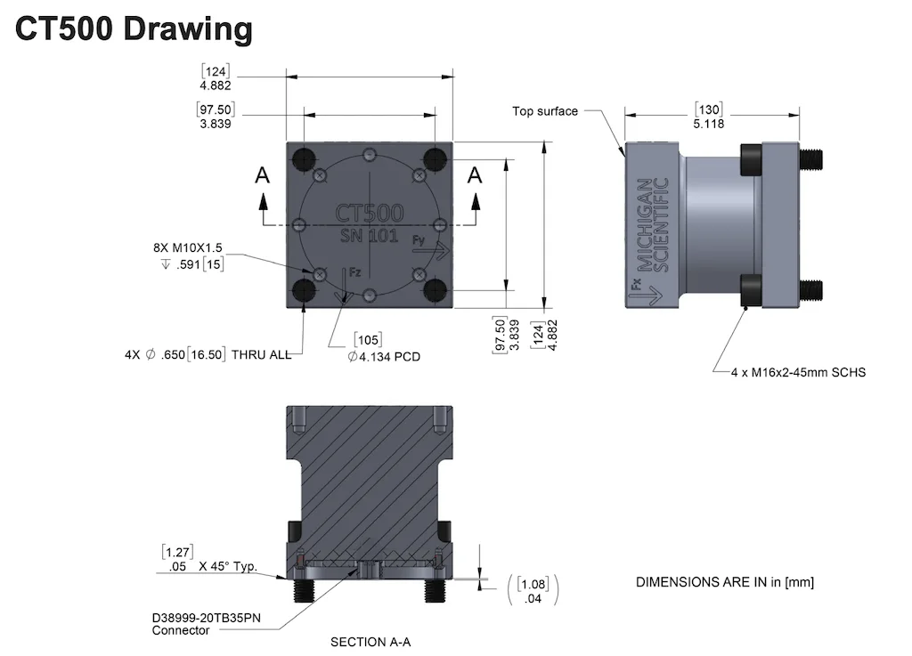
- 124 × 124 mm
- face of one cell
What a load cell wall measures
Crash and impact tests add the force on the barrier to the accelerations measured on the vehicle and its structure. Three-axis load cells are assembled side by side into an impact measuring panel.
Each cell measures the force it receives in three directions: Fx, the impact axis, with the larger range, and Fy and Fz. The panel therefore gives three force signals per cell.
Building the wall from 124 mm cells
The face of the CT500 is 124 × 124 mm, a standard size, so several cells assemble into one panel. In the Instrumented Crash Barrier System, 64 cells are bolted to a 1 m² stainless steel plate at 125 mm spacing, with the signal wires routed inside the plate. Several systems side by side make a larger barrier face. Mounting plates, cables and a data acquisition system can be supplied with the cells.
- 01
Set the range of the cells
The standard range is ± 500 kN on X, the impact axis, and ± 125 kN on Y and Z. The nominal load can be changed on request.
CT500 crash barrier load cell - 02
Assemble the cells into a panel
The cells are bolted side by side to a rigid mounting plate, which can be supplied with them.
- 03
Connect each cell
Each cell is a strain gauge transducer with a MIL connector. It takes a 10 V DC bridge excitation and gives an output of 3.5 or 4.5 mV/V.
- 04
Record the three forces of each cell
The signals go to the data acquisition system, which can be supplied with the cells.
Range, accuracy and environment of the CT500
The cell has a stainless steel housing sealed to IP66, with all electronics inside, and it is temperature compensated.
| Axes | 3 (Fx, Fy, Fz) |
|---|---|
| Measuring range, Fx (impact axis) | ± 500 kN |
| Measuring range, Fy and Fz | ± 125 kN |
| Non-linearity | < ± 0.5 % FSO |
| Hysteresis | 0.5 % FS |
| Natural frequency | > 1 800 Hz |
| Output signal | 3.5 or 4.5 mV/V |
| Supply voltage | 10 V DC |
| Dimensions | 124 × 124 × 130 mm |
| Operating temperature | −40 to 125 °C |
| Protection class | IP66 |
| Calibration | ISO 17025 certificate |
Other multi-axis load cells in a crash test
The barrier is not the only place where forces are measured. TR3D three-axis load cells are bolted between a seat and its mountings to record the forces the mountings take in a crash. The TR3D series covers 1.1 to 444 kN per axis.
Where moments have to be separated from the forces, a six-axis load cell measures three forces and three moments at once. The TR6D-C-40K has a range of 178 kN and 9.5 kN·m per axis and is fatigue rated.
What you get
The force of the impact on the barrier, in three directions, for each cell of the panel. The cells, their mounting plates, the cables and the data acquisition system can come as one supply, and each cell is delivered with an ISO 17025 calibration certificate.
Frequent questions
What size is a crash barrier load cell?
The CT500 measures 124 × 124 × 130 mm. Its 124 × 124 mm face is a standard size, so several cells assemble into an impact measuring panel.
How much force can one cell of a load cell wall take?
The CT500 has a measuring range of ± 500 kN on X, the impact axis, and ± 125 kN on Y and Z. The nominal load can be changed on request.
Does a crash barrier load cell measure transverse forces?
Yes. The CT500 is a three-axis load cell. It measures Fx, the impact axis, up to ± 500 kN, and Fy and Fz up to ± 125 kN.
Similar applications
All applications-
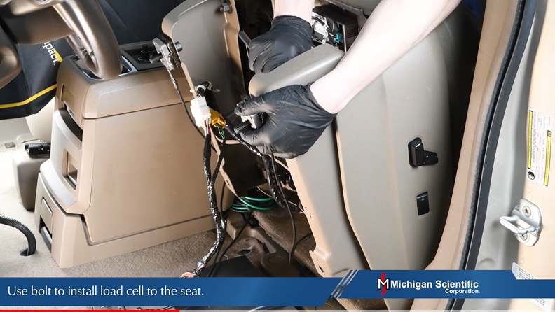 Component Seat forces The three forces each seat mounting takes while driving and in a crash, without changing the driving position.
 -
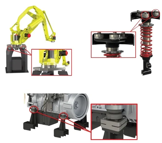 Rig Force and moment load platform Net forces and net moments on a system, calculated from four three-axis load cells.
 -
 Component Engine mount loads The three forces each mount passes to the frame during start-up, acceleration and gear shifts.