
Application · EMC
Monitoring equipment signals over fiber during bulk current injection tests
In brief
A bulk current injection (BCI) test checks the immunity of wiring harnesses to radio frequency interference. To know whether the equipment under test degrades, its signals have to be watched during the test, from inside a high electromagnetic field. A fiber-optic link carries the signal out of the high-field area without the interference corrupting it. Michigan Scientific fiber-optic systems are hardened for both immunity and emissions.
- 10 kHz to 200 MHz
- radio frequency range given for BCI tests
- 200 V/m
- EMC validation of the links, 500 kHz to 18 GHz
- 1 Mbit/s
- CAN bus carried over fiber
What a BCI test checks
A BCI test injects radio frequency current, given as 10 kHz to 200 MHz, into the lines of a wiring harness. The test shows whether this interference degrades the performance of the equipment under test.
Engineers use the result to reduce the effect of outside electromagnetic sources on the vehicle electronics. BCI tests are run on complete vehicles and on components.
The monitoring link must not be part of the problem
To see a degradation, the signals of the equipment have to be read while the interference is applied. The source of the signal sits in a high electromagnetic field. If the field corrupts the measurement on its way out, a deviation can no longer be read as an effect on the equipment.
The first requirement is therefore a signal that the field does not change. The second is that the link adds no emissions of its own to the test.
A transmitter in the field, a receiver outside it
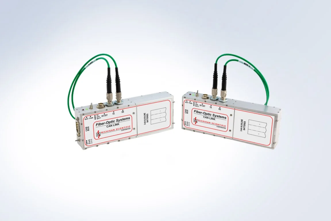
The electrical signal is converted to light next to the equipment under test and travels over a fiber-optic cable, which the field does not disturb. The modules at each end are shielded and filtered against electromagnetic and radio frequency interference, for both immunity and emissions, and validated for EMC up to 200 V/m from 500 kHz to 18 GHz.
- 01
Choose the link for the signal
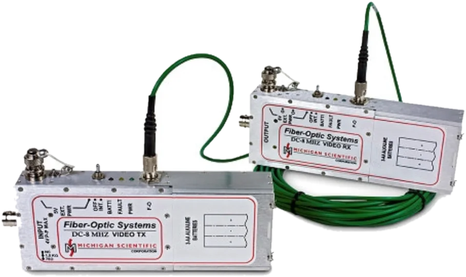
Each kind of signal has its link: analog voltage, CAN bus, video or light level. The table below lists them.
Fiber-optic systems - 02
Place the transmitter at the equipment under test
The transmitter sits in the high-field area and converts the signal to light.
- 03
Run the fiber to the low-field area
The receiver, outside the field, returns an electrical signal to the monitoring equipment.
- 04
Or send a signal in
The links are used to monitor signals or to source them, at component level and at system level.
One link for each kind of signal
The values below come from the Michigan Scientific product data for each link.
| FO-ST and FO-SR-04 | Two analog channels, DC to 20 kHz |
|---|---|
| FO-HBST and HBSR | One analog voltage, DC to 1 MHz |
| FO-CAN | Differential CAN bus, up to 1 Mbit/s |
| FO-HBAVT and HBAVR | ±1 V analog or NTSC/PAL video, DC to 8 MHz |
| FO-ALS | Illuminance of lamps and indicators, 1 to 10 000 lx |
What a stable signal makes possible
When the link does not change the signal, the engineer can decide whether the equipment degraded during the test and work on reducing the interference. Michigan Scientific also offers these systems to laboratories working toward EMC laboratory certification.
What you get
The signals of the equipment under test, readable during the whole test, in a low-field area. A change in the signal can then be attributed to the equipment and not to the monitoring link.
Frequent questions
Why use a fiber-optic link to monitor signals during a BCI test?
The electromagnetic field does not disturb a fiber-optic cable. The signal is converted to light next to the equipment under test, so a change in the signal can be attributed to the equipment and not to the monitoring link.
Can a CAN bus be monitored during a BCI test?
Yes. The FO-CAN link carries a differential CAN bus over fiber at up to 1 Mbit/s.
What frequency range does a BCI test cover?
The radio frequency signals applied to the wiring harness in a BCI test are given as 10 kHz to 200 MHz.
What field strength are the fiber-optic links validated for?
The EMC validation of the Michigan Scientific fiber-optic links is 200 V/m, from 500 kHz to 18 GHz. The modules are hardened for both immunity and emissions.
Similar applications
All applications-
 Medical Medical equipment Small tension loads, multi-axis forces on prostheses and clean temperature signals, for medical and pharmaceutical equipment.
 -
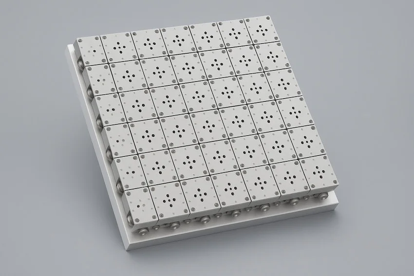 Crash Crash barrier loads Impact force on a crash barrier, measured in three directions by a panel of 124 mm load cells.
 -
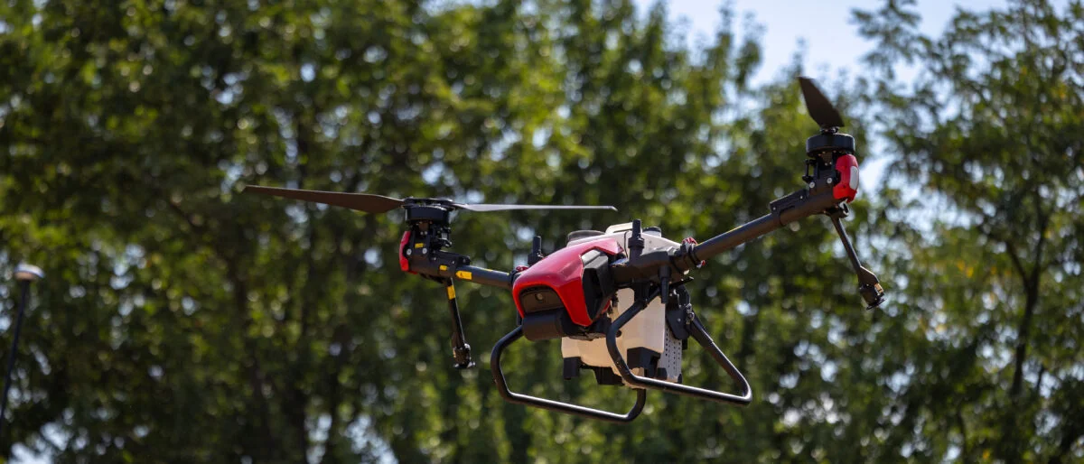 Component Drone payload and landing loads The forces in a drone's payload path, at the moment of release and at touchdown, measured without changing the geometry or adding mass.