
Measuring forces and torques on tractors and farm machines at work
In brief
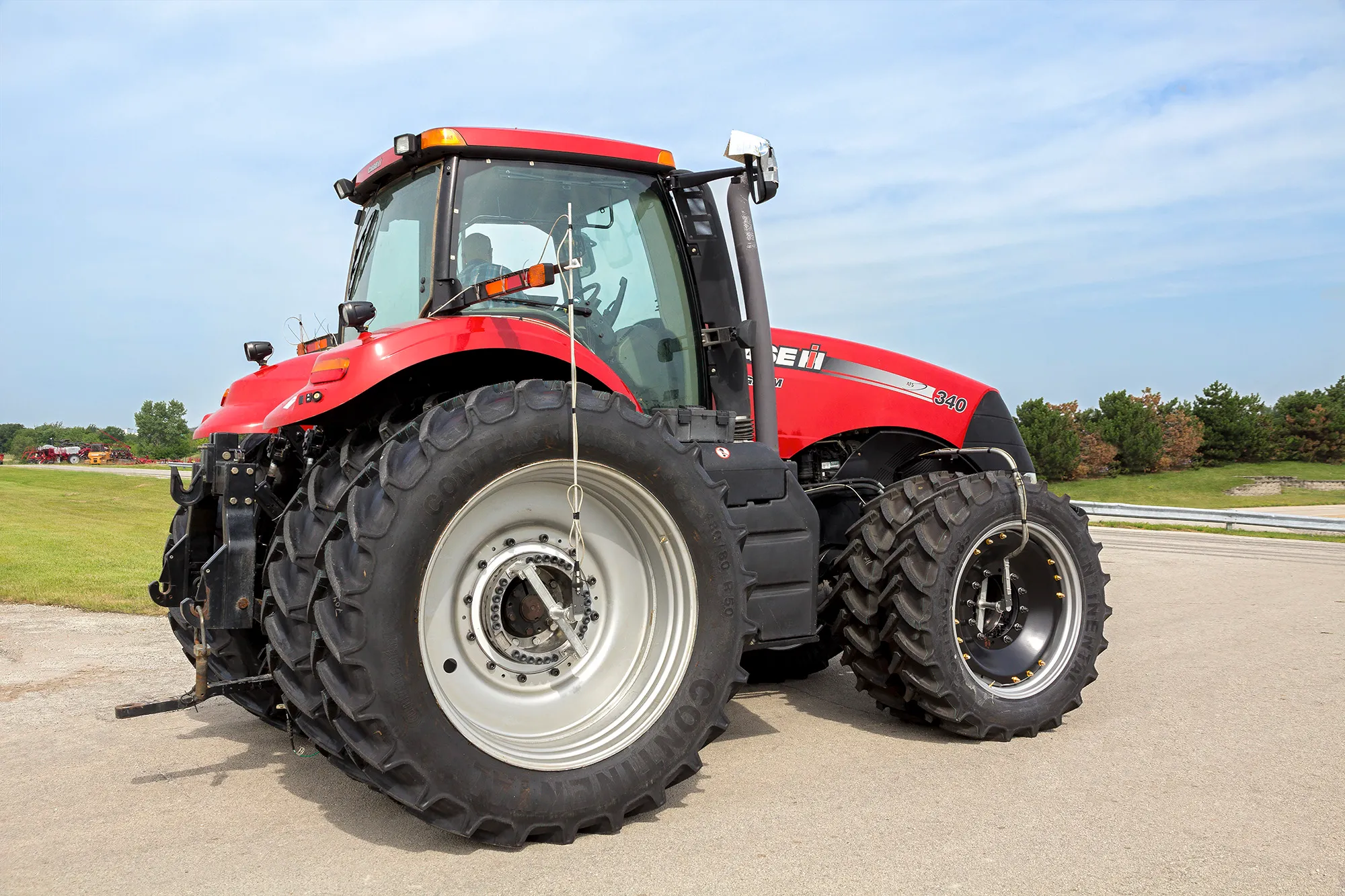
The loads of a tractor and its implement are measured on the machine at work. A wheel force transducer replaces the wheel center and gives the three forces and three moments at the wheel. A wheel torque transducer gives the drive and brake torque. A PTO transducer splined between the tractor and the implement gives the torque and the speed of the power take-off shaft. Where no transducer fits, on a clutch, inside a gearbox or on a pulley, the part is strain gaged and a slip ring or a telemetry transmitter brings the signal off it.
- 222 to 445 kN
- Fx and Fz capacity, LW-2T-50K to LW-2T-100K
- 19.5 in
- smallest rim for the LW-2T-50K and the TW-2T-50K
- ± 5 000 N·m
- highest full-scale torque of the PTO transducers
Measurement points
Force enters the tractor at the wheels, power leaves through the power take-off, and the working parts of the implement carry their own loads. Each point takes a different transducer, and several of them rotate, so the signal has to reach a recorder that does not.
The loads are higher than on road vehicles. The wheel force transducers for large farm equipment are rated 222 to 445 kN in Fx and Fz, and the wheel torque transducers up to 81 kN·m.
Instrumentation
| Wheel forces and moments | LW-2T-50K: 222 kN Fx and Fz, 111 kN Fy, 68 kN·m, rims of 19.5 in and larger · LW-2T-100K: 445 kN Fx and Fz, 225 kN Fy, 135 kN·m, rims of 22.5 in and larger · four-arm bridges, −40 to 125 °C, slip ring version |
|---|---|
| Wheel torque | TW-2T-50K: 67 kN·m · TW-2T-60K-S: 81 kN·m · rims of 19.5 in and larger · four-arm strain gage bridge |
| PTO torque and speed | PTO: ± 2 500 or ± 5 000 N·m, integrated telemetry, 60 ppr encoder, removable splined ends for types 1, 2 and 3 · PTO2: integrated B4-2W/E60 slip ring, one spline size per transducer |
| Forces on working parts | TR3D three-axis load cells, 1.1 to 444 kN per axis; five- and six-axis load cells for forces and moments |
| Gaged components | clutch, gearbox shafts, pulleys and gears, on the customer's own parts |
Signal path
The wheel force transducer amplifies its signals on the transducer; they leave the wheel through a slip ring or a telemetry package and reach the CT2 or CT3 interface box, which does the coordinate transformation and the crosstalk compensation in real time and outputs analog, CAN and Ethernet. The wheel torque transducer uses a weatherproof slip ring, encoder and amplifier assembly, or telemetry.
The PTO transducer carries its own signal path: induction-powered telemetry on the PTO, a B4-2W/E60 slip ring with a 60 ppr encoder on the PTO2. On a gaged clutch, gearbox shaft or pulley, an end-of-shaft slip ring, a tubular slip ring that slides over the shaft or a clamp-on telemetry transmitter brings the bridge signal out.
Gaged components
Some measurements cannot be made with a catalog part. The component itself is then fitted with strain gages and calibrated, and becomes the transducer. Past work on agricultural equipment includes an instrumented clutch, gages applied inside a gearbox, and pulley and gear transducers made from customer components. When the gaged part rotates, an end-of-shaft slip ring with 4 to 10 circuits, a tubular slip ring with a bore of 30 to 81.3 mm, or a clamp-on transmitter on shafts of 25 mm and more carries the bridge signal to the recorder.
Procedure
- 01
Choose the wheel transducers
By the loads expected and the rim size. The hub and rim adapters are made from the drawings of the original rim.
Choosing a wheel force transducer - 02
Fit the PTO transducer
Female spline on the tractor shaft, male spline on the implement, both ends locked. Nothing is modified on either machine.
PTO torque transducers - 03
Gage the parts without a transducer
Strain gages on the clutch, the gearbox shaft or the pulley, calibrated before the test.
Strain gage services - 04
Record in the field
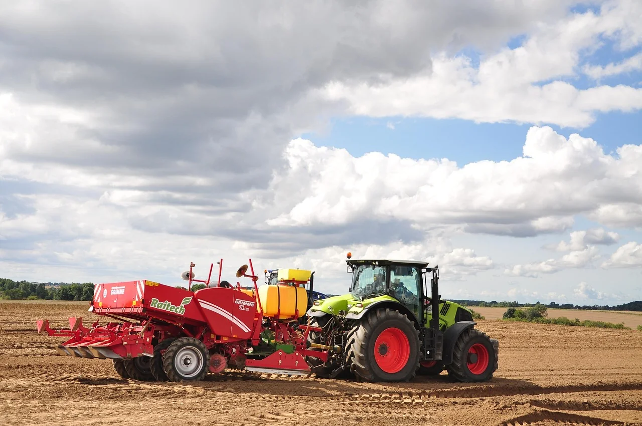
Durability, handling and brake runs with the wheel transducers; PTO torque and speed during implement work.
Result
The forces and torques the machine sees in the field, at the wheels, at the power take-off and on its working parts. Wheel force data feeds durability and handling work, wheel torque data the brake and driveline development, and PTO torque times speed gives the power delivered to the implement.
Frequent questions
How is PTO power measured on a tractor?
A PTO transducer splined between the tractor and the implement measures torque and speed; their product is the power delivered at the shaft. Full scale is ± 2 500 or ± 5 000 N·m, with a 60 ppr encoder.
What size of wheel force transducer fits a tractor wheel?
The LW-2T-50K, 222 kN in Fx and Fz, fits rims of 19.5 in and larger; the LW-2T-100K, 445 kN, rims of 22.5 in and larger.
How is torque measured on a tractor clutch or inside a gearbox?
The part itself is strain gaged, because no standard transducer fits there. An end-of-shaft slip ring, a tubular slip ring or a clamp-on telemetry transmitter carries the signal to the recorder.
How are the forces on the working parts of a farm machine measured?
With multi-axis load cells in the load path, three-axis TR3D from 1.1 to 444 kN per axis, or five- and six-axis models when the moments are needed.
Similar applications
All applications-
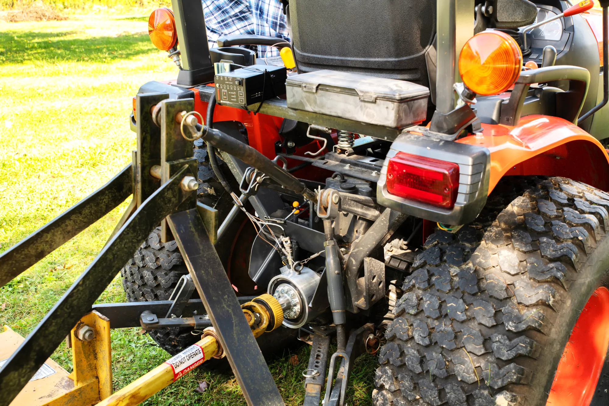 Agriculture PTO torque and power The torque and speed that the tractor delivers to the implement, measured during real field work.
-
 Durability Wheel loads on the road Three forces and three moments at each wheel, recorded while the vehicle is driven.
-
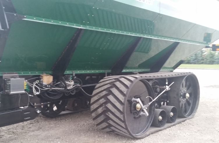 Off-highway Tracked vehicles Forces on the road wheels, the idler and the sprocket of a tracked vehicle, to validate the running gear model.