
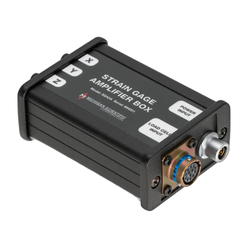
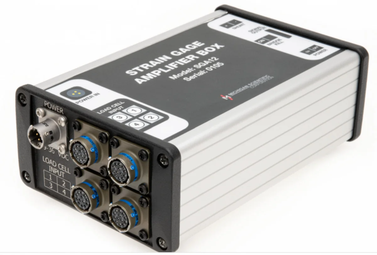
SGA3A three-channel strain gage amplifier box
Three-channel strain gage amplifier box for one Michigan Scientific three-axis load cell, with bridge excitation, a ± 10 V output per axis and remote shunt calibration.
- 3
- Channels
- ± 10 V
- Output
- ± 15 V DC
- Supply voltage
- ± 5 V or ± 2.5 V
- Bridge excitation
- Frequency response, −3 dB20 kHz (gain 1000) · 40 kHz (gain 100)
- Gain100 and 2000 V/V
- Shunt calibrationremote, positive and negative
- Operating temperature−40 to 125 °C
One box per three-axis load cell
The SGA3A is a three-channel strain gage amplifier box for Michigan Scientific three-directional load cells. Its three independent miniature amplifiers each provide bipolar bridge excitation of ± 5 V (10 V total) or ± 2.5 V, a stable differential amplifier and a remotely activated 100 kΩ or 1 MΩ shunt resistor for span verification. The output is ± 10 V, with a 20 kHz response at gain 1000 and 40 kHz at gain 100. It runs on ± 15 V DC and operates from −40 to 125 °C. Other channel counts are built on request, and optional summation wiring lets one box serve load cells used in parallel.
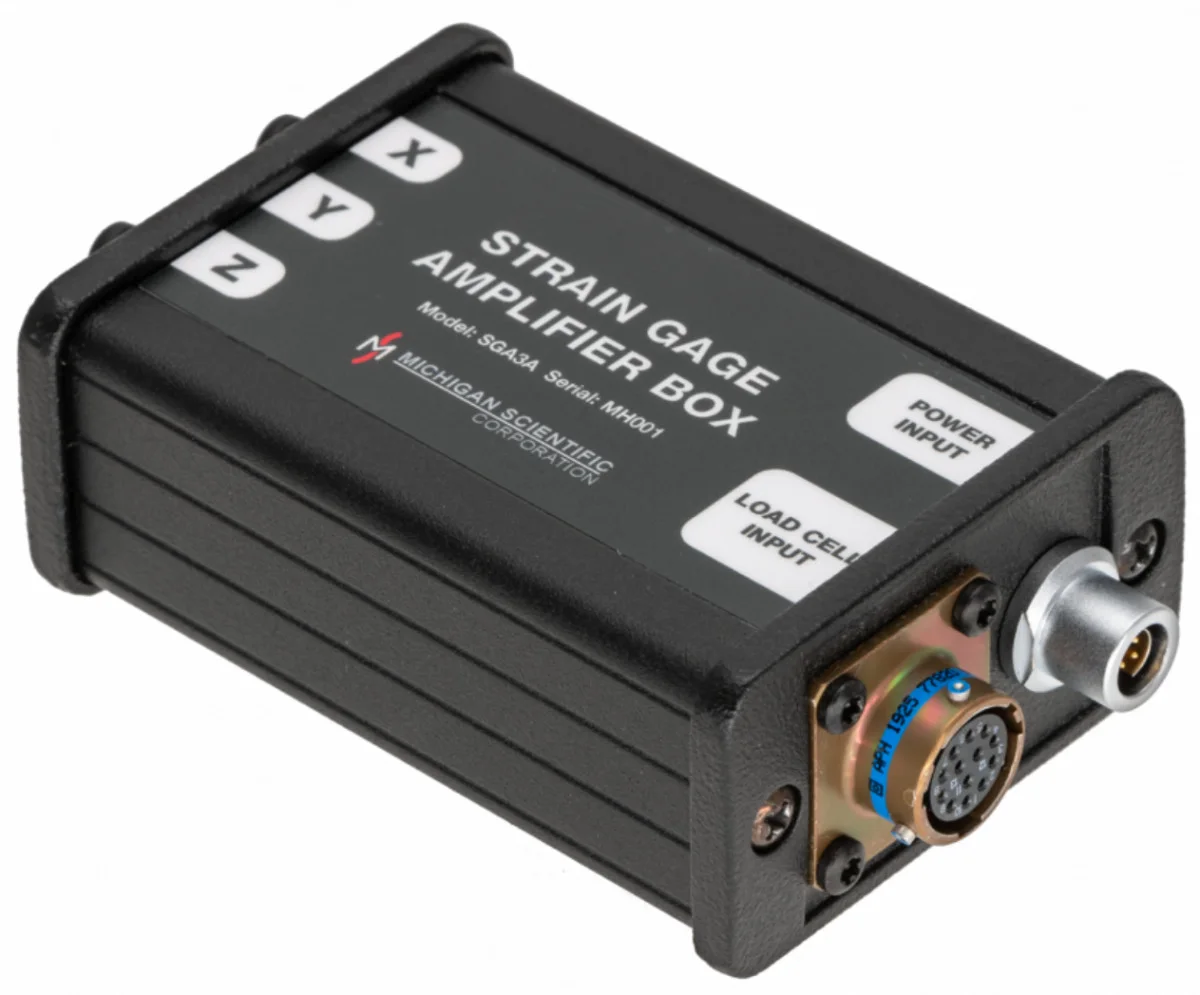
Michigan Scientific selects the gain and shunt resistors for the chosen load cell and installs them at the factory; the box label names the load cell it was calibrated with. The load cell plugs into the load cell input, ± 15 V DC enters through the power input connector, supplied with its mating cable, and the X, Y and Z force outputs are taken on BNC connectors. With power on, the signals are zeroed with no load applied. A PS-DC or PS-AC power supply applies the shunt calibration with the flip of a switch.
It is used with a TR3D three-axis load cell to measure engine mount forces, pintle hitch forces in real towing, and forces on a robot arm or a prosthetic foot.
Specifications
| Channels | 3 (independent; other counts on request) |
|---|---|
| Input | Strain gage bridge (one three-axis load cell; optional summation wiring for several load cells in parallel) |
| Output | Analog voltage |
| Output range | −10 to 10 V |
| Bandwidth | 40 kHz (−3 dB at gain 100; 20 kHz at gain 1000) |
| Noise, referred to input | ≤ 0.7 µV (p-p, 0.01 to 10 Hz) |
| Gain | 100 to 2 000 V/V (fixed values 100 and 2000) |
| Gain setting | Fixed (gain and shunt precision resistors selected for the load cell, factory installed) |
| Shunt calibration | Positive · Negative · Remote |
| Shunt resistor | 100 · 1 000 kΩ |
| CMRR | 160 dB |
| Shunt accuracy | ≤ 0.1 % |
| Supply voltage | 15 V (dual supply, ± 15 V DC) |
| Excitation voltage | 5 to 10 V (± 2.5 or ± 5 V, bipolar DC constant voltage; remote on/off) |
| Supply current | 45 mA (per rail, 3 channels, plus bridge load; 60 mA during shunt calibration) |
| Excitation current limit | 84 mA (at 10 V excitation) |
| Excitation accuracy | ≤ 0.4 % |
| Excitation temperature coefficient | ≤ 0.0005 %/°C |
| Operating temperature | −40 to 125 °C |
| Compensated temperature | −40 to 85 °C |
Request a quote
Resources
Datasheets and manuals
Drawings
None for this product.
CAD models
None for this product.
Related applications
-
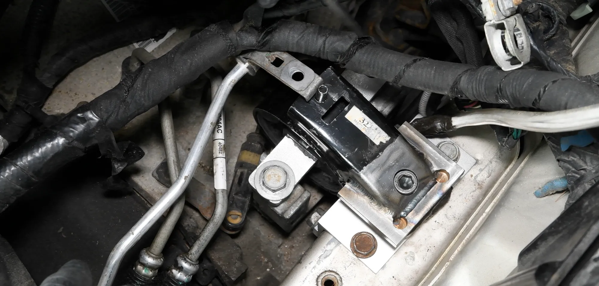 Component Engine mount loads The three forces each mount passes to the frame during start-up, acceleration and gear shifts.
-
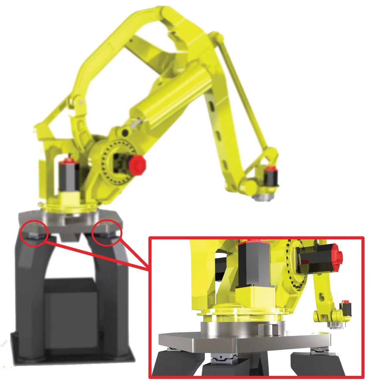 Component Robotics and prosthetics Forces in three directions, and moments, on a robot arm or a prosthetic foot, from a load cell small enough to fit in the assembly.
-
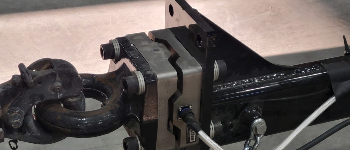 Towing Pintle hitch forces The three forces between towing vehicle and trailer, recorded in real towing situations.
A question on this product?
Describe the measurement. An application engineer answers.
More details to give? Use the full contact form.