
The essential
A strain gage bridge delivers a few millivolts. An amplifier next to the bridge provides a precise excitation, raises the signal to ± 10 V and applies the shunt calibration, before the signal crosses a slip ring or a long cable. Where it mounts narrows the choice first, then the excitation, the gain and the bandwidth.
Why amplify at the sensor?
Because a high-level signal resists what it meets on the way to the recorder. An amplifier on the rotating side turns the bridge output into a ± 10 V signal before it crosses the rings, which reduces the errors from temperature gradients across the slip ring and from interference. It is worth it with low strain levels, electrically noisy environments, high speeds and vibration.
- Noise referred to input: 0.7 µV peak to peak from 0.01 to 10 Hz on the AMP-SG-M1 and AMP-SG-U2.
What is inside the amplifier?
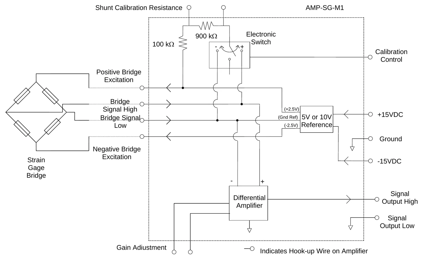
Four functions, described in the operator's manuals of the AMP-SG-M1 and AMP-SG#-U2: a precision low drift reference that excites the bridge, a differential amplifier, a shunt calibration resistor switched by a control line, and a ± 15 V supply with its common. The block diagram shows them.
- Excitation: a 5 or 10 V reference, split ± 2.5 V or ± 5 V around the ground reference. A full bridge is needed for the amplifier to regulate it; completion resistors for a quarter or half bridge are added outside.
- Gain: 100 V/V with the gain wires open, 2 000 V/V with the wires shorted, any value between with a resistor across them. The manual gives the formula.
- Shunt calibration resistance: 1 MΩ with the shunt wires open, 100 kΩ shorted, any value between with a resistor. For both resistors, Michigan Scientific advises 0.01 % tolerance and less than 25 ppm/°C.
- Output: read Output High against Output Low, not against the power common, to keep the voltage drop along the common out of the measurement.
Where does it mount?
On the part, on the slip ring rotor, inside the slip ring, or in a box on the stationary side. The place decides the family.
- On the part: AMP-SG-M1, 31.75 × 20.32 × 6.35 mm and 14.17 g with wired connections; AMP-SG-MH, 40.54 × 25.4 × 6.86 mm and 11 g with solder terminals. One channel each.
- On the rotor of an SR series slip ring: AMP-SG-U2 (one bridge), AMP-SG2-U2 (two) and AMP-SG3-U2 (three), Ø 53 mm modules that pilot on the rotor and stack.
- Inside the slip ring: S6/G and S8/2G of the S-Series, Short S6/G and Short S8/2G, and the sealed B6-2W/AMP-SG2 and BA-T-1.2W of the B-Series.
- In a box, for load cells: SGA3A, three channels for one three-axis load cell; SGA12A, twelve channels for up to four, also built with 3, 6 or 9.
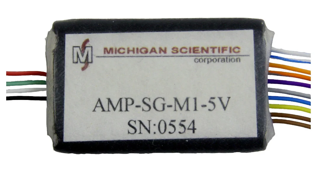 On the partAMP-SG-M1
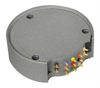 On the SR rotorAMP-SG-U2
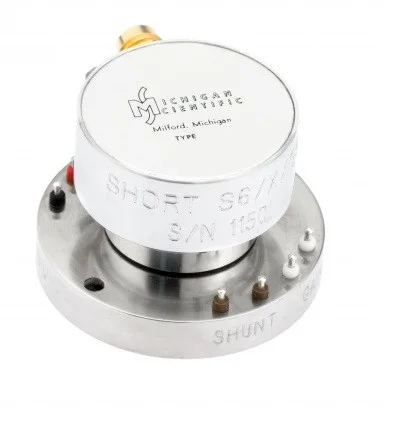 In the slip ringShort S
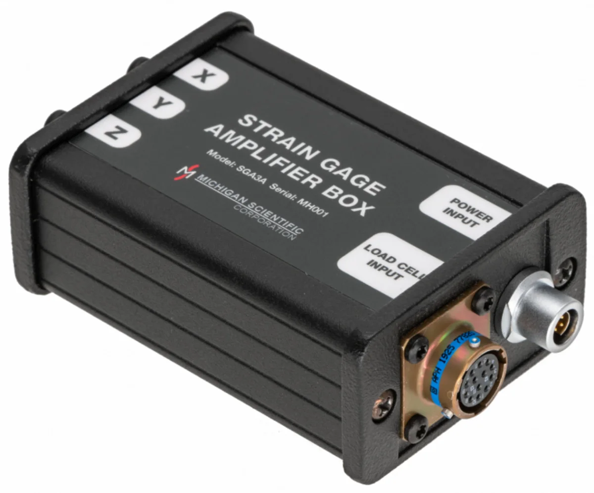 In a boxSGA3A
Which bridge excitation?
A bipolar DC constant voltage, 5 V (± 2.5 V) or 10 V (± 5 V) on most models. The bridge output is proportional to the excitation, and so is the current the bridge draws.
- 5 or 10 V: AMP-SG-M1, AMP-SG-MH, AMP-SG2-U2, AMP-SG3-U2, SGA3A, SGA12A, and the slip rings with a built-in amplifier (G5 or G10 in the reference).
- AMP-SG-U2: 5 V standard, 10, 17 or 20 V in the -10, -17 and -20 versions; the excitation current goes from 42 mA standard to 167 mA on -20.
- Bridges of 350 Ω and above suit the amplifiers built into S-Series slip rings.
Which gain?
The one that brings the full scale signal of the bridge close to the ± 10 V output. The bridge output at full scale is its sensitivity times the excitation: a 2 mV/V bridge at 5 V gives 10 mV, and a gain of 1 000 brings it to 10 V.
- AMP-SG-M1, AMP-SG-MH and AMP-SG-U2 family: 100 or 2 000 V/V by jumper, any value between by an external resistor.
- SGA3A and SGA12A: Michigan Scientific selects the gain and shunt resistors for the load cell and installs them in the box.
- Gain accuracy at 25 °C, typical: ± 0.05 % at gain 100, ± 0.50 % at gain 1 000 (AMP-SG-U2, SGA3A).
What is shunt calibration?
A check of the whole chain without applying a load. On command, the amplifier connects a known resistor in parallel with one arm of the bridge. The bridge goes out of balance by a known amount and the output steps, as it would under a known load. The data acquisition system is calibrated or checked on that step, with the transducer in place.
- + 15 V on the calibration control line connects the resistor from positive excitation to positive signal, − 15 V from positive excitation to negative signal: a positive and a negative step.
- The size of the step: a 100 kΩ shunt across one 350 Ω arm gives about 0.87 mV/V, that is 4.4 mV at 5 V excitation and 4.4 V at a gain of 1 000. A 1 MΩ shunt gives ten times less.
- The calibration of a transducer gives its shunt calibration equivalent: the load that produces the same output as the shunt resistor. Scaling the channel on it gives the load units.
- Bridge excitation off: with the ± 15 V supplies reversed, the amplifier runs with the bridge excitation killed, which measures its own offset, the noise floor and magnetic pickup. The PS-AC does it with a switch.
- With transducers wired in parallel, the shunt step falls with the number of bridges; the guide on transducers in parallel gives the rule.
How much bandwidth?
20 kHz at −3 dB on most models, and less at high gain on the single-channel AMP-SG-U2. Check it against the frequency of the event to be measured, at the gain chosen.
- AMP-SG-M1, AMP-SG-MH, AMP-SG2-U2 and AMP-SG3-U2: 20 kHz.
- AMP-SG-U2: 10 kHz at gain 100, 1 kHz at gain 1 000; higher bandwidths on request.
- SGA3A: 40 kHz at gain 100, 20 kHz at gain 1 000.
How is it powered and controlled?
Spinning amplifiers run on ± 15 V DC brought through the slip ring, with a calibration control line. Each strain gage amplifier uses five lines: + 15 V, − 15 V, power common, calibration control and signal common, then one ring per channel.
- PS-AC control unit: ± 15 V, 0.8 A, enough for 18 strain gage amplifiers at 5 V excitation on 350 Ω bridges, with switches for bridge excitation on/off and positive or negative shunt calibration.
- SGA3A: ± 15 V DC from a PS-AC or PS-DC control unit. SGA12A: internal power supply, 10 to 36 V DC.
- Operating case temperature: −40 to 125 °C for the AMP-SG-M1, −55 to 125 °C for the AMP-SG-U2, −50 to 100 °C for the SGA12A; each datasheet gives the range within specification.
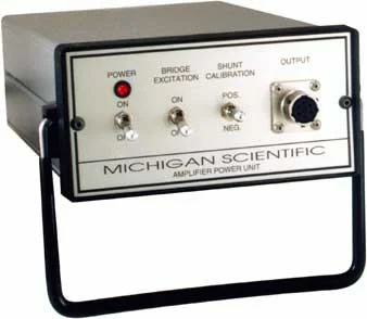 Control unitPS-AC
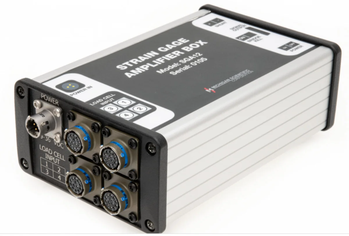 Internal supplySGA12A
Analog or digital output?
Every amplifier above gives an analog ± 10 V per channel. When the recorder reads CAN, the MUX modules excite, condition and digitize the bridges on one CAN 2.0 or CAN FD bus, up to 8 ksps, stackable to 48 channels.
- MUX-FB-12: twelve full-bridge strain gage sensors.
- MUX-BC350-12: twelve quarter-arm strain gages, bridge completion included.
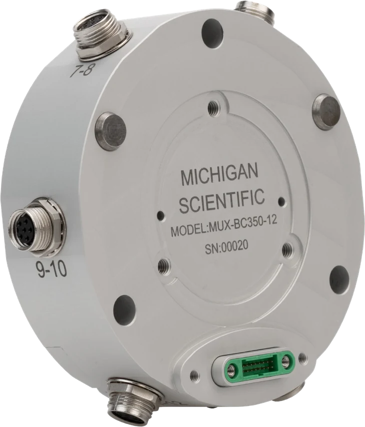 One module12 channels
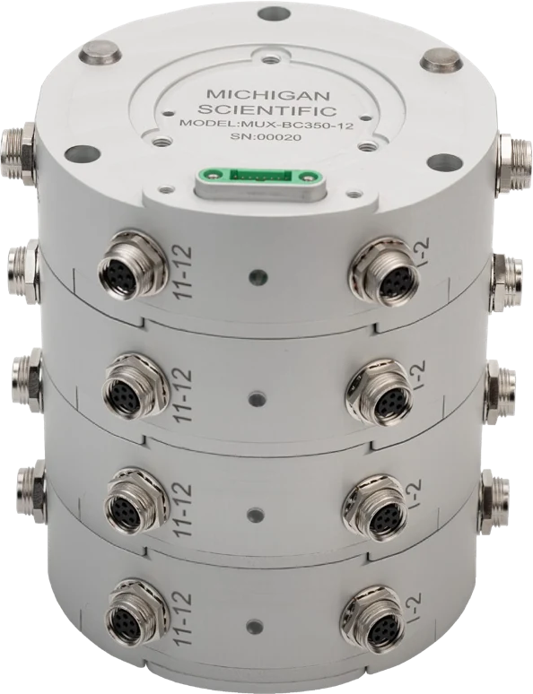 Four stacked48 channels
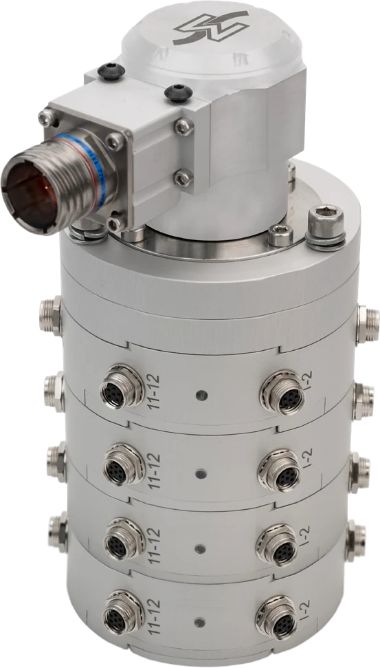 Under a slip ringSR10AW/WFT
To remember
- Amplify at the sensor, above all through a slip ring.
- On the part: AMP-SG-M1 or AMP-SG-MH. On an SR rotor: AMP-SG-U2, 1 to 3 bridges per module. For load cells: SGA3A or SGA12A.
- Gain = 10 V / (sensitivity × excitation); 100 to 2 000 V/V.
- Shunt calibration checks the whole chain on a known step, without a load.
- 20 kHz on most models; on the AMP-SG-U2, 1 kHz at gain 1 000.
- Five service lines through the slip ring, then one ring per channel.