
LW50 wheel force transducer
Six-axis wheel force transducer for passenger cars and light-duty trucks, 50 kN radial and 25 kN lateral, IP67, rated −40 to 177 °C, with slip ring or telemetry.
- 50 kN
- Fx, Fz capacity
- 25 kN
- Fy capacity
- 6.5 kN·m
- Moment capacity
- ≤ 0.25 % FS
- Non-linearity
- OutputsFx Fy Fz · Mx My Mz
- Also measuredX and Z acceleration (X, Y, Z on the LW50) · wheel speed and angle
- Signal outputanalog · CAN · Ethernet · CAN FD and EtherCAT on the CT3
Wheel force transducer for cars, 50 kN, up to 177 °C
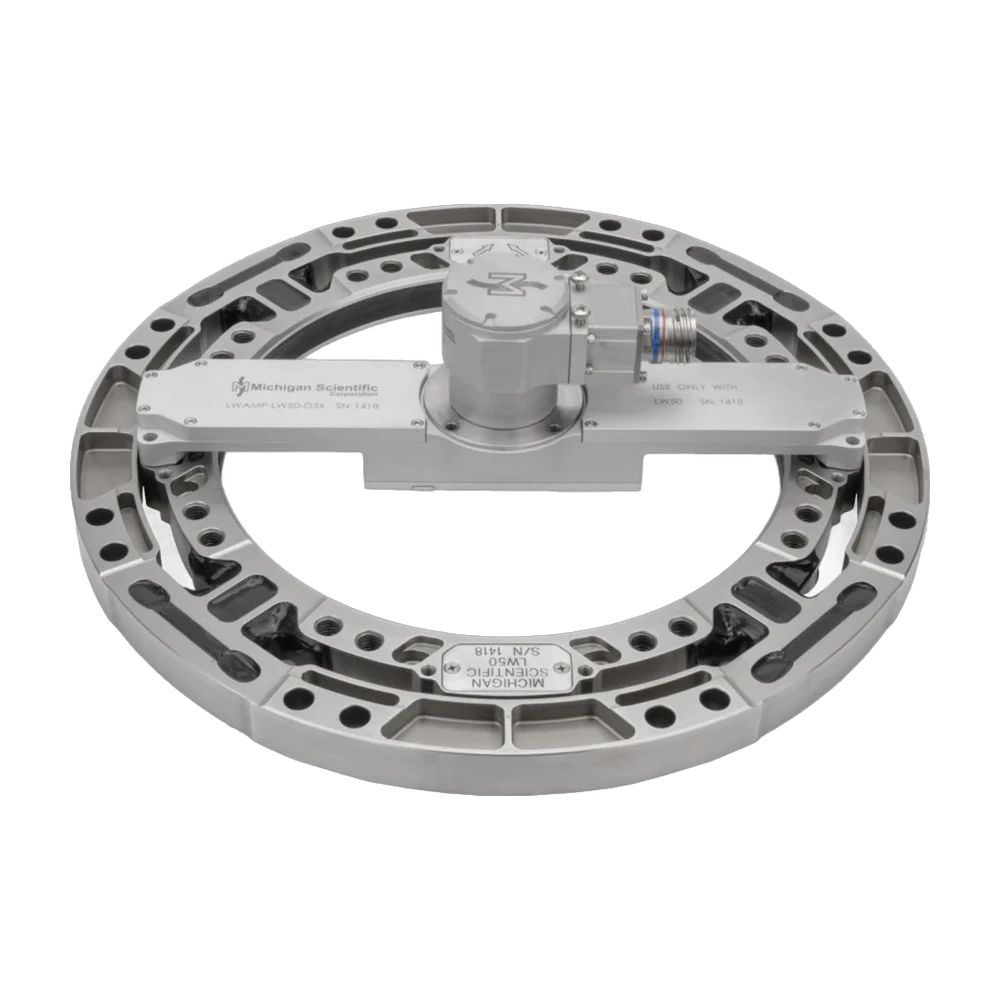
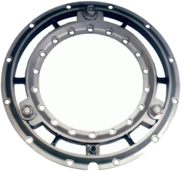
The LW50 measures all the wheel forces and moments on passenger cars and light-duty trucks. It is rated 50 kN (11,200 lbf) on Fx and Fz, 25 kN (5,620 lbf) on Fy and 6.5 kN·m on all three moments, for a static weight of 1,020 kg. Non-linearity and hysteresis are 0.25 % of full scale or less, cross-axis sensitivity after correction 0.4 % or less. The IP67 transducer, Ø 342.90 × 21.59 mm, weighs 4.4 kg, operates from −40 to 177 °C and adapts to 12 in and larger wheels.
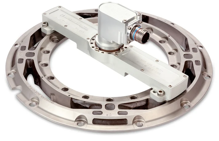
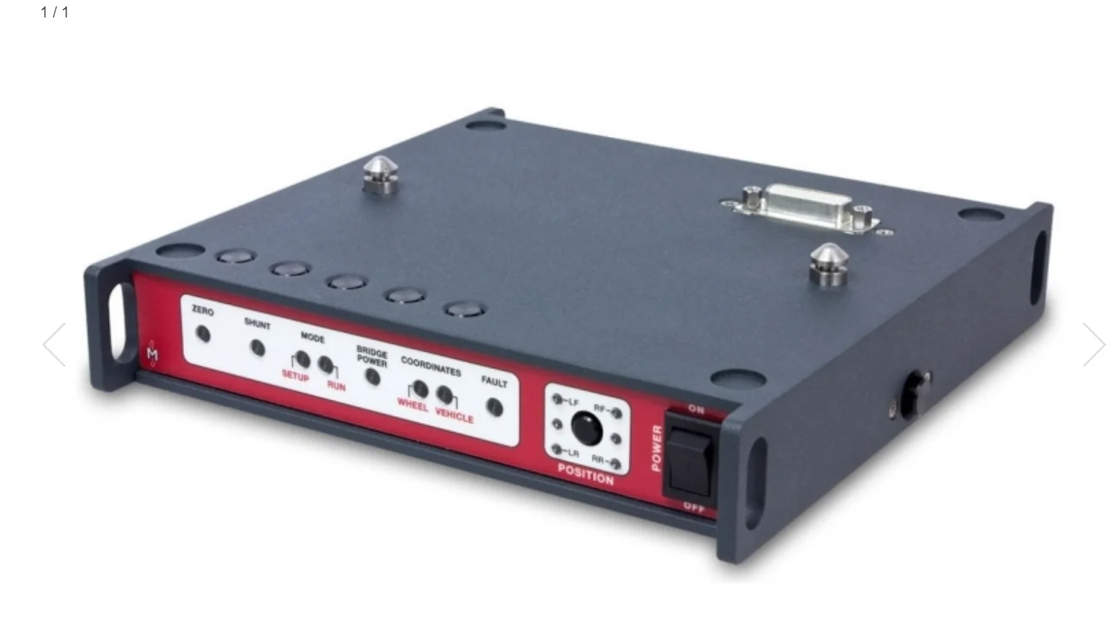
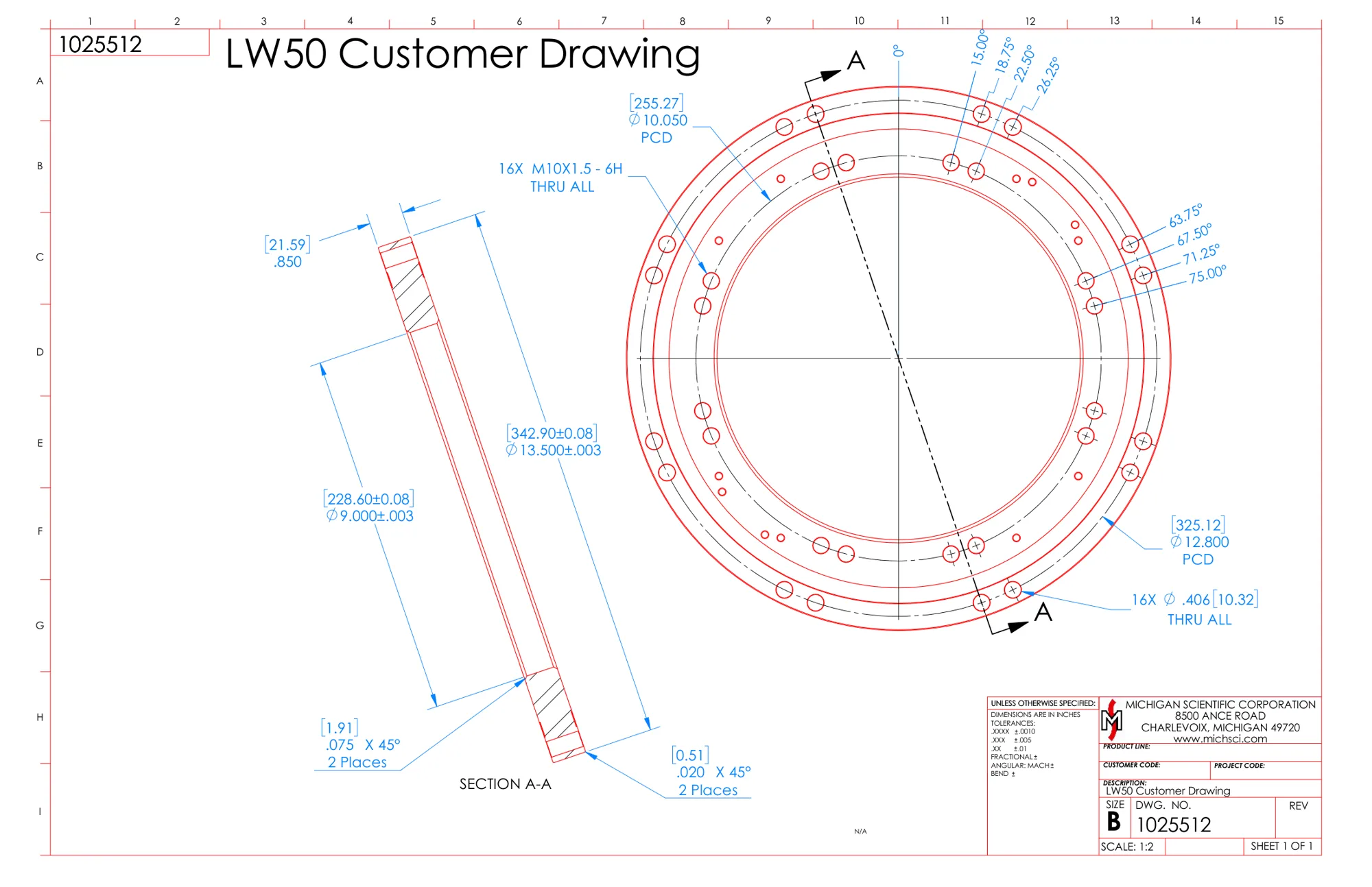
Its inner circle has sixteen M10 × 1.5 threaded holes, its outer circle sixteen through holes. With the outboard slip ring, the amplifier package mounts onto the transducer, adds X, Y and Z accelerations up to ±100 g and digitizes the signals; a high-resolution optical encoder gives position and speed, at 0.17°. The inboard telemetry package uses a magnetic encoder and an induction-powered stator. The CT3 box resolves the loads in real time, with zero, shunt calibration and zero angle functions, a front display and a web page over USB.
It is designed for the harshest track and off-road measurements on passenger cars and light-duty trucks, and for non-spinning applications that monitor and control laboratory test rigs.
Specifications
| Measured quantities | Fx · Fy · Fz · Mx · My · Mz |
|---|---|
| Force capacity | Fx 50 · Fy 25 · Fz 50 kN |
| Moment capacity | Mx 6 500 · My 6 500 · Mz 6 500 N·m |
| Max static load | 1 020 kg |
| Non-linearity | ≤ 0.25 % FS |
| Hysteresis | ≤ 0.25 % FS |
| Crosstalk | ≤ 0.4 % FS (after correction) |
| Angle resolution | 0.17° |
| Axes | 6 |
| Accelerometer range | 100 g (X, Y and Z) |
| Output | CAN FD · CAN · Ethernet · EtherCAT · Analog voltage (CAN 2.0; EtherCAT and analog with optional modules) |
| Signal transmission | Slip ring · Telemetry (slip ring outboard; telemetry inboard) |
| Shaft diameter | 228.6 mm (center bore) |
| Mounting fasteners | 16 × M10 × 1.5 |
| Rim fasteners | 16 × Ø 10.32 mm (through) |
| Bolt circle | 255.27 mm |
| Rim bolt circle | 325.12 mm |
| Dimensions | Ø 342.9 × 21.59 mm |
| Weight | 4.4 kg |
| Operating temperature | −40 to 177 °C |
| Protection | IP67 |
| Interface box | CT3 |
| Vehicles | Passenger cars · Light trucks |
| Rim size | 12 in (and larger) |
Request a quote
Unusual bolt pattern, motorsport hub, agricultural wheel: we build it around your wheel.
Resources
Datasheets and manuals
Drawings
CAD models
Guides and notes
Related applications
-
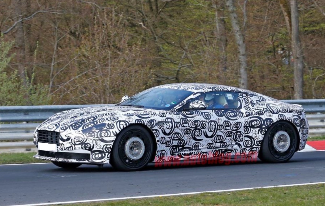 Durability Wheel loads on the road Three forces and three moments at each wheel, recorded while the vehicle is driven.
-
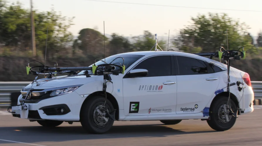 Dynamics Vehicle dynamics The forces and moments at each wheel while the vehicle brakes, turns and changes lane.
-
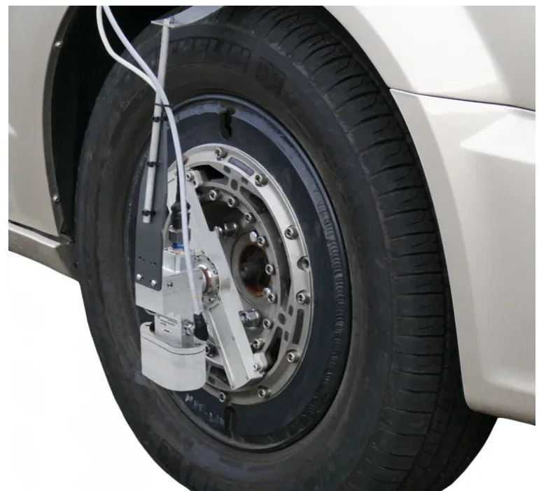 Dynamics Side slip angle Side slip angle read without contact by an optical sensor, on a wheel or on the vehicle body.
-
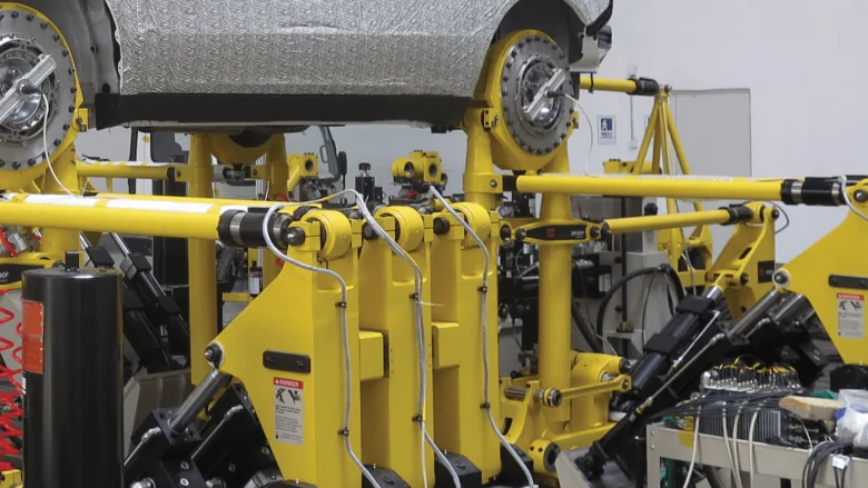 Test rig Road simulators The loads measured at the wheel on the road, and the proof that the simulator reproduces them.
If a six-axis wheel is not what you need
- Torque only TW series wheel torque transducers
Drive and brake torque My at the wheel, 237 N·m to 81 kN·m.
- Signals from the series wheel Wheel instrumentation system
Strain gages, thermocouples and wheel speed, on the wheel the vehicle already has.
- Force on a part, not a wheel TR3D-B three-axis load cells
Three orthogonal forces from 1.1 to 71 kN per axis.
A question on this product?
Vehicle, wheel size, expected loads. An application engineer answers.
More details to give? Use the full contact form.