
Fiber-optic systems
A signal out of an EMC chamber, unchanged.
The link carries an electrical signal over fiber from a source in a high electromagnetic field or an anechoic chamber to the monitoring bench outside. The modules are validated for EMC up to 200 V/m, 500 kHz to 18 GHz. Used in reverberation chambers, for bulk current injection tests, and for A2LA or AEMCLRP laboratory work.
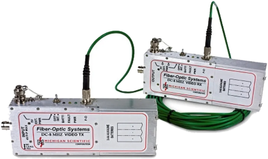
- DC to 8 MHz
- analog bandwidth over fiber (FO-HBAVT/HBAVR)
- 1 to 2
- channels per link
- Analog · CAN · video
- signal types
Light does not pick up a field.
The link replaces the copper between the equipment under test and the monitoring bench.
In an EMC test, a copper cable is an antenna: it changes the test and corrupts the signal. A fiber does neither, so the monitoring stays stable while the field is on.
Advantages
- The transmitterIt sits next to the equipment under test, inside the chamber, and converts its electrical signal into light. Its shielding protects it from EMI and EMP; it runs on 3 AA batteries.
- The fiberGlass carries no current. It neither picks up the field nor brings interference back into the chamber.
- The receiverIn the low-field area, it converts the light back into an electrical signal for your monitoring equipment. The links also work the other way, to source a signal into the equipment under test.
Fiber-optic link selection
Bandwidth, battery life. Models meeting every criterion, ranked by margin.
Set the criteria. Closest models first.
| Model | Bandwidth (kHz) | Battery life (h) | Actions |
|---|---|---|---|
| FO-HBST and HBSR | 1 000 kHz (from DC) | — | Request a quote Datasheet |
| FO-ST and FO-SR-04 | 20 kHz (from DC) | 100 h (minimum) | Request a quote Datasheet |
| FO-ALS and FO-SR-04 | 1.5 | 60 | Request a quote Datasheet |
| FO-CAN and FO-CAN-R | — | 30 h (minimum) | Request a quote Datasheet |
| FO-HBAVT and HBAVR | 8 000 kHz (from DC) | 11 h (minimum) | Request a quote Datasheet |
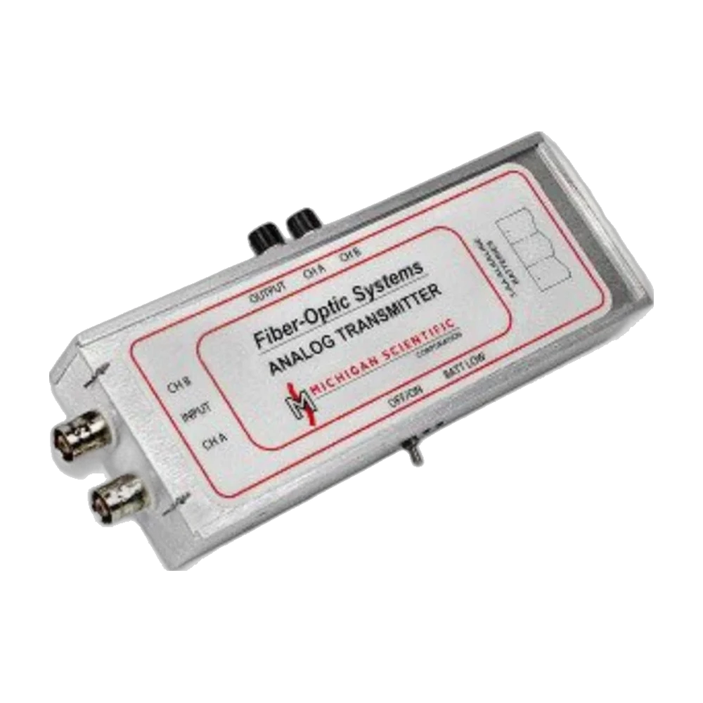
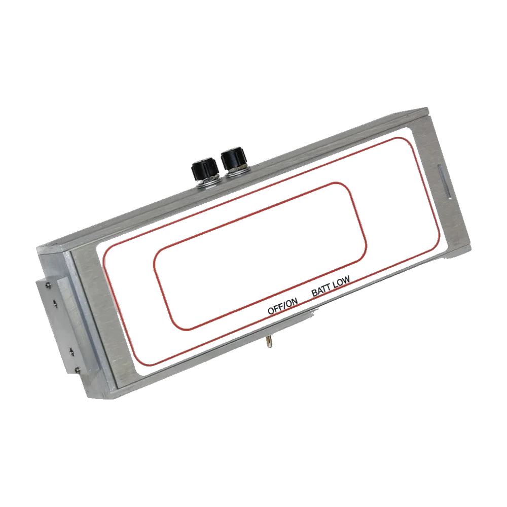
No catalogue model meets every criterion. Custom versions exist: ask us.
Signal type and field strength known? Send them, an application engineer selects the link. Send the data
Services around the product
Support, calibration and custom parts, from the same team.
-
 Service Technical support An application engineer answers, and a loan unit covers an urgent breakdown. See the service
-
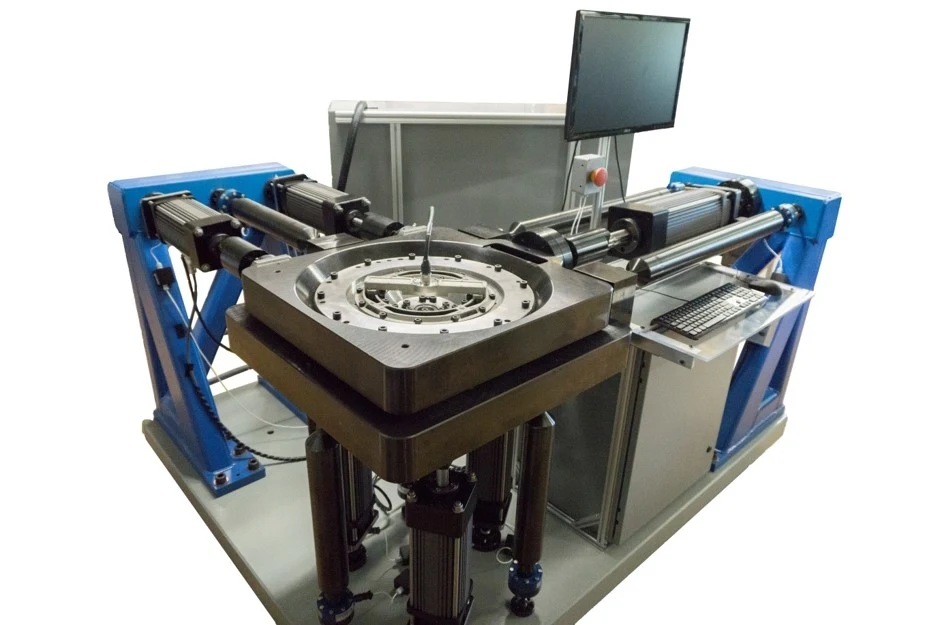 Service Calibration Accredited ISO/IEC 17025 calibration, 1 to 6 axes, for Michigan Scientific transducers and those of other manufacturers. See the service
-
 Service Custom transducers Your own part strain gaged and calibrated, or a transducer designed for your space and load case. See the service
Technical data and documents
- Detail page
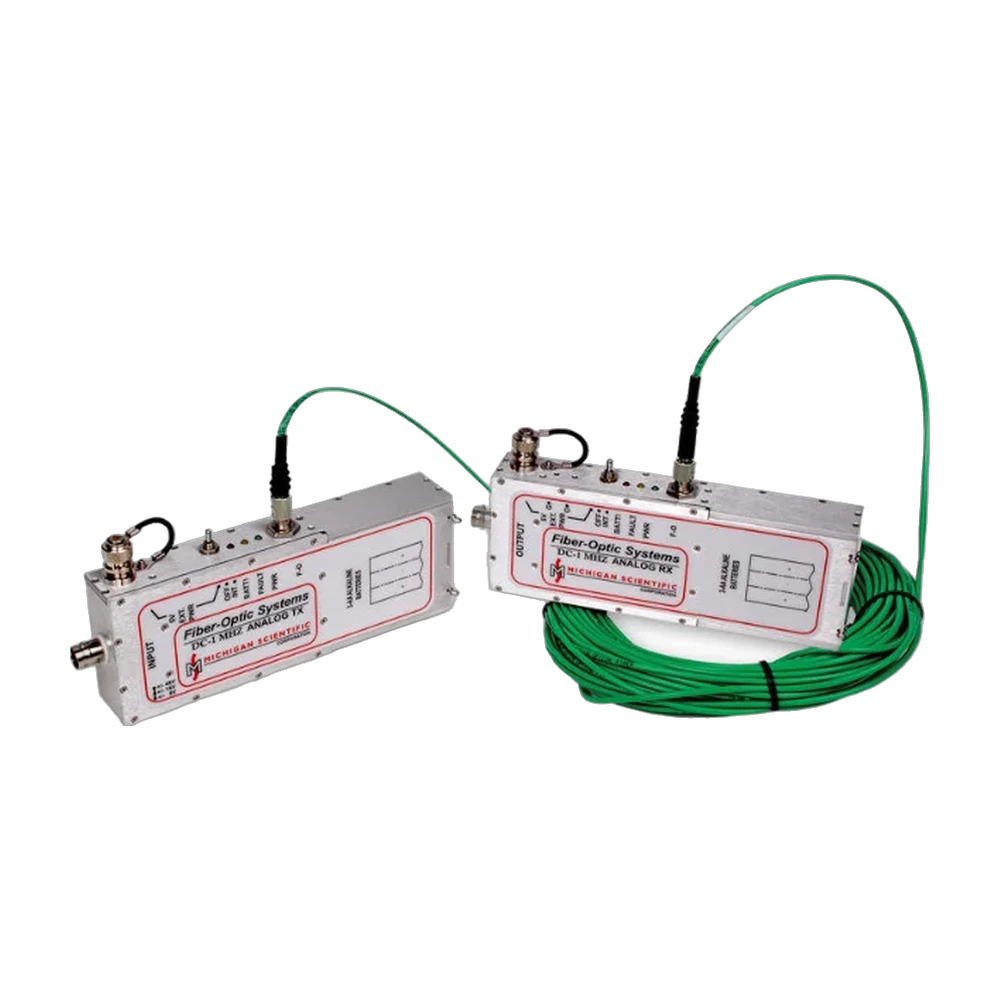
FO-ALS and FO-SR-04
Changes in the brightness of a lamp or indicator during an EMC test, measured from 1 to 10 000 lx and sent out over fiber.
Open the FO-ALS and FO-SR-04 - Detail page
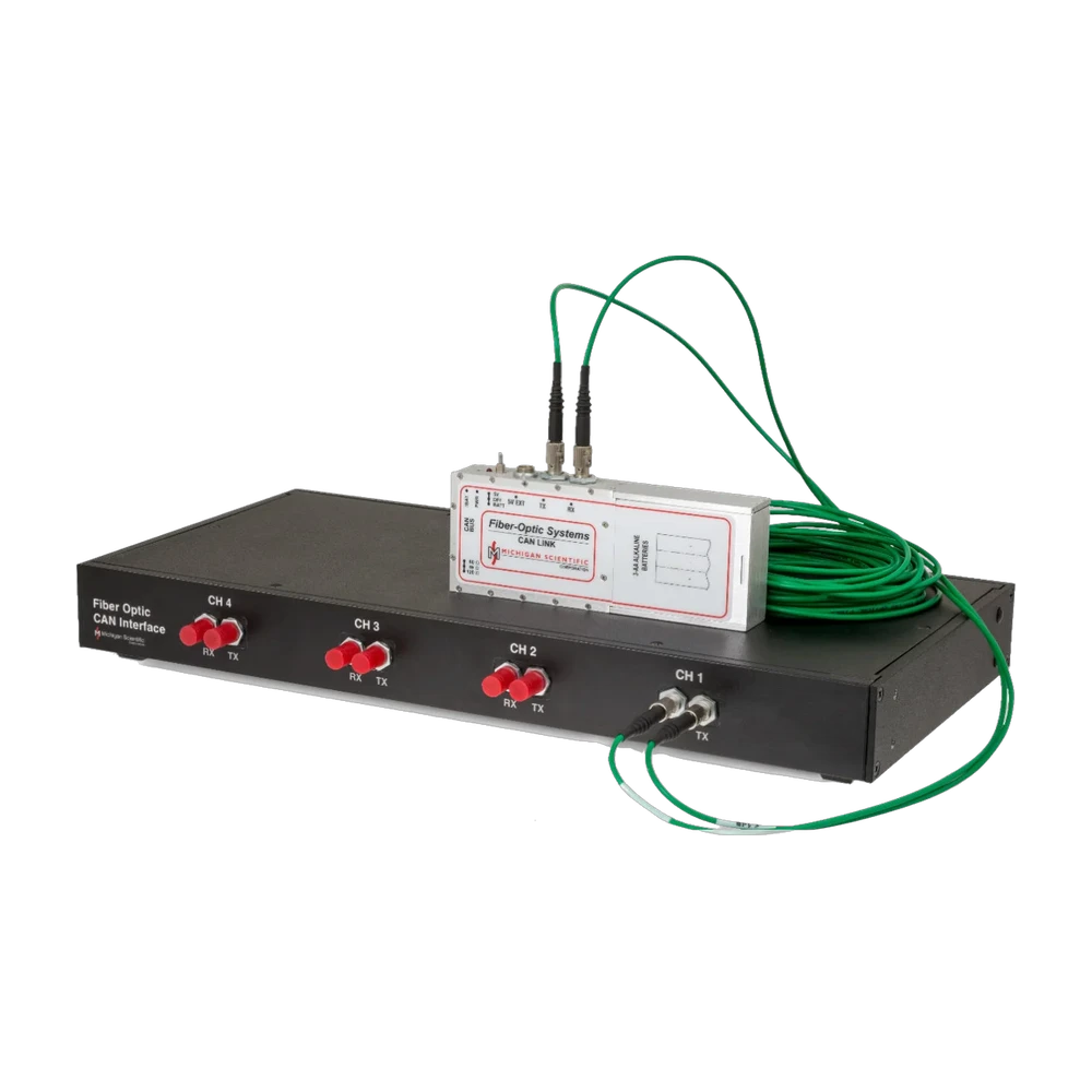
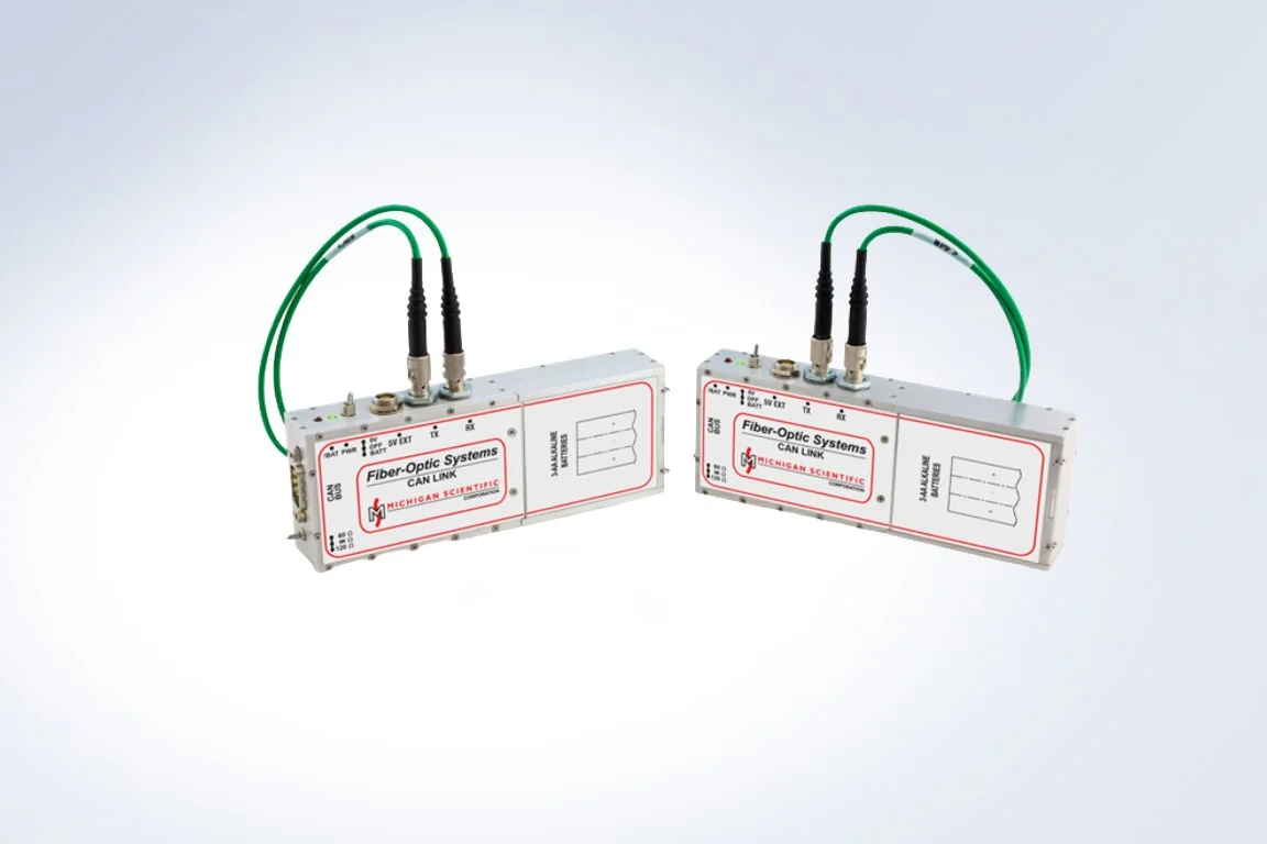
FO-CAN and FO-CAN-R
A CAN bus carried over fiber at up to 1 Mbit/s, to monitor or stimulate equipment during EMC tests.
Open the FO-CAN and FO-CAN-R - Detail page
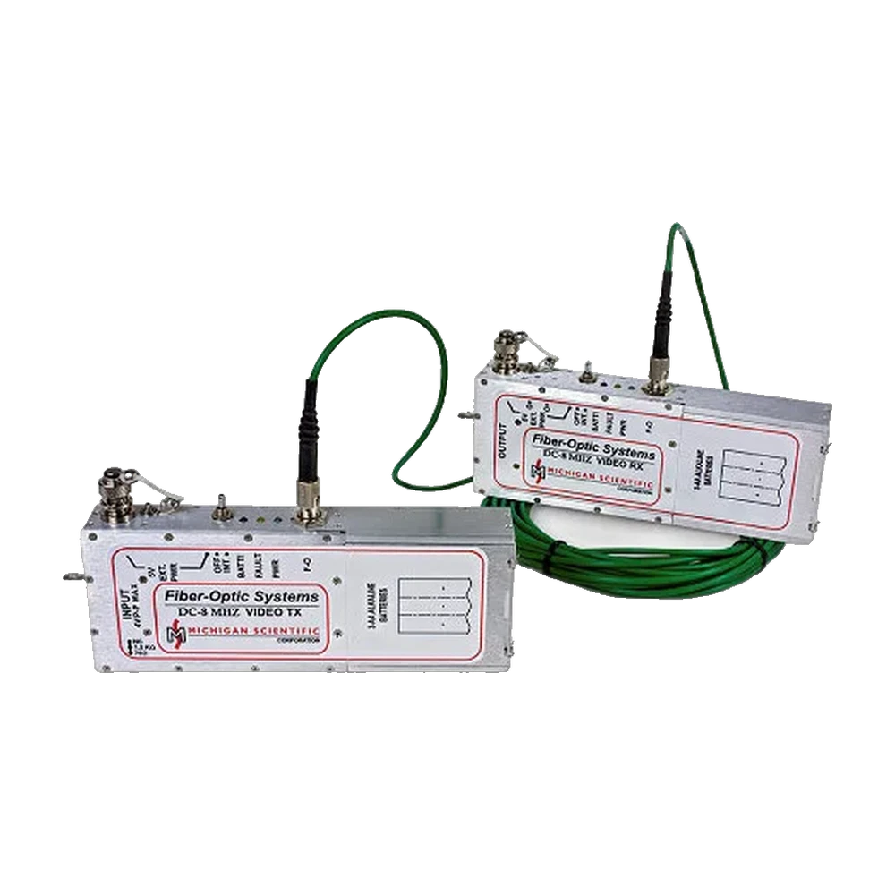
FO-HBAVT and HBAVR
A ±1 V analog or NTSC/PAL video signal carried over fiber, to or from the equipment under test.
Open the FO-HBAVT and HBAVR - Detail page
FO-HBST and HBSR
An analog voltage from DC to 1 MHz carried over fiber, to or from the device under test during EMC tests.
Open the FO-HBST and HBSR
Technical support
An application engineer answers within 24 hours on working days. When equipment fails during a campaign, diagnosis is remote and a loan unit can be shipped, depending on the project.
How support works- < 24 h
- first answer from an application engineer
- Over 30
- wheel force transducers in the loan and rental fleet
- 1 to 2 weeks
- typical calibration turnaround
Which link for your chamber?
Signal type, bandwidth, number of channels, test standard. An application engineer answers with a reference and a price.
More details to give? Use the full contact form.