
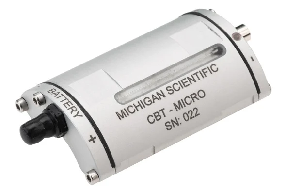

CBT-micro clamp-on battery telemetry
Battery-powered clamp-on telemetry transmitter for one full strain gage bridge with one output, 90 g in an IP67 housing that straps to shafts of 25 mm or more.
Battery-powered clamp-on telemetry transmitter for one full strain gage bridge with three outputs at 2, 4 and 20 mV/V full scale, 90 g in an IP67 housing.
- 1
- Outputs
- 8 h
- Battery life
- 1 kS/s
- Sample rate
- 25 mm
- Min shaft diameter
- 3
- Outputs
- 6 h
- Battery life
- 1 kS/s
- Sample rate
- 25 mm
- Min shaft diameter
- Resolution14 bit
- HousingIP67
- Operating temperature−20 to 60 °C
One bridge, one output, 90 g
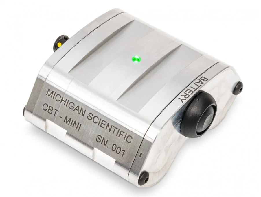
The CBT-MICRO is a wireless, battery-powered transmitter for one full strain gage bridge of 350 Ω or more. Its M540 telemetry transmitter excites the bridge, conditions the signal with a fixed gain, 20 mV/V full scale as standard, and transmits it digitally on a 2.4 GHz link at 1 kS/s, or 7 kS/s on request, with 14-bit resolution; the receiver gives a ±10 V analog output, with a total delay under 200 µs. Two 10440 rechargeable lithium-ion batteries last 8 h. The IP67 housing weighs 90 g with batteries and runs from −20 to 60 °C, the battery limit.
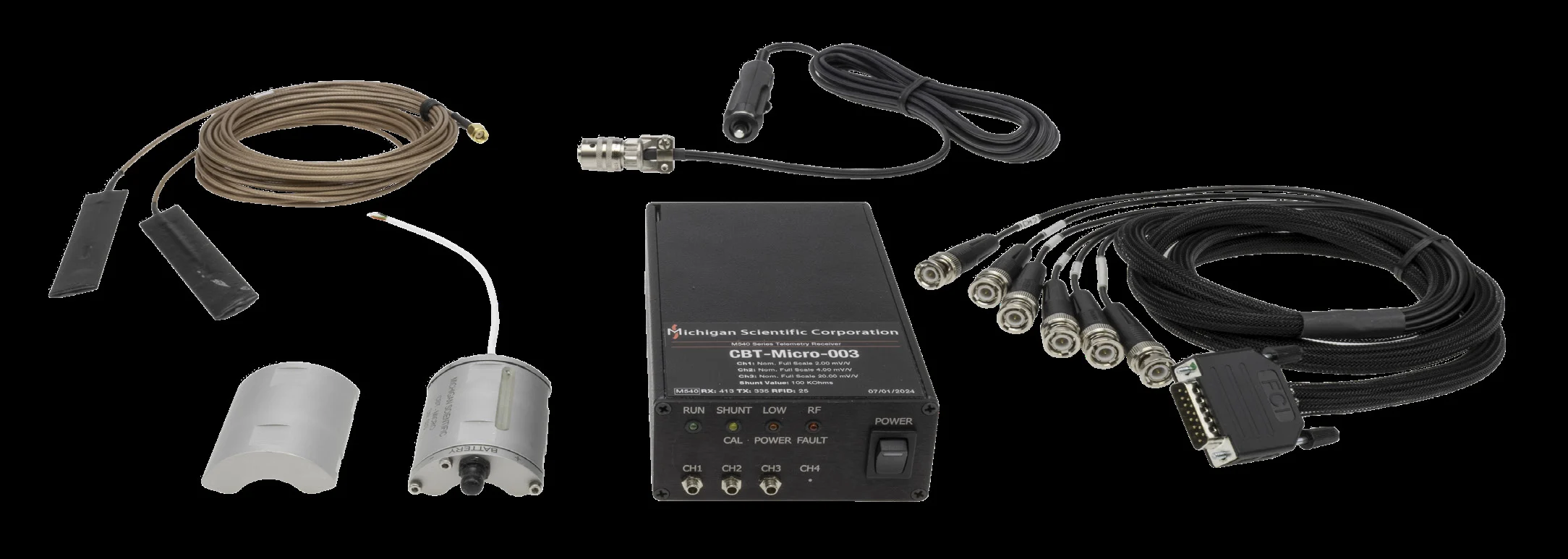
The bridge is wired to the lead leaving the CBT-MICRO (P+, S+, S−, P−), and the batteries go in under the battery lid, held by two M2.5 screws. The unit is laid on fusion tape and secured with cable ties, hose clamps or steel bands, chosen from the manual's table of shaft speed and diameter, with a counterweight 180° opposite when the shaft must be balanced. Pressing the switch powers the transmitter and starts a 3 s shunt calibration sequence, with a 49.9 kΩ resistor as standard. The M540 receiver takes 9 to 36 V DC and two antennas placed on opposite sides of the shaft; its RF FAULT LED guides their positioning, and a front-panel potentiometer trims the zero.
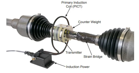
Its datasheet shows it on an automotive half shaft, with the strain gage bridge on the shaft and the counterweight opposite the transmitter.
One bridge, three ranges, 90 g
The CBT-MICRO-3 is a wireless, battery-powered transmitter for one full strain gage bridge of 350 Ω or more. Its M540 telemetry transmitter excites the bridge, conditions the signal on three outputs, each with its own fixed gain, 2, 4 and 20 mV/V full scale as standard, and transmits it digitally on a 2.4 GHz link at 1 kS/s, or 7 kS/s on request, with 14-bit resolution; the receiver gives a ±10 V analog output on each output, with a total delay under 200 µs. Two 10440 rechargeable lithium-ion batteries last 6 h, or 4.5 h at 7 kS/s. The IP67 housing weighs 90 g with batteries and runs from −20 to 60 °C, the battery limit.
The bridge is wired to the lead leaving the CBT-MICRO-3 (P+, S+, S−, P−), and the batteries go in under the battery lid, held by two M2.5 screws. The unit is laid on fusion tape and secured with cable ties, hose clamps or steel bands, chosen from the manual's table of shaft speed and diameter, with a counterweight 180° opposite when the shaft must be balanced. Pressing the switch powers the transmitter and starts a 3 s shunt calibration sequence, with a 100 kΩ resistor as standard. The M540 receiver takes 9 to 36 V DC and two antennas placed on opposite sides of the shaft; its RF FAULT LED guides their positioning, and a front-panel potentiometer trims the zero.
Its datasheet shows it on an automotive half shaft, with the strain gage bridge on the shaft and the counterweight opposite the transmitter.
Specifications
| Channels | 1 |
|---|---|
| Input | Strain gage bridge (full bridge) |
| Output | Analog voltage (1 output) |
| Output range | −10 to 10 V |
| Sample rate | 1 kHz (default; 7 kHz available) |
| Resolution | 14 bit |
| Latency | ≤ 0.2 ms |
| Bridge input range | 20 mV/V (standard; other ranges available) |
| Shunt resistor | 49.9 kΩ (standard; other values available) |
| RF band | 2.4 GHz |
| RF channels | 16 |
| Transmission distance | 3 to 4 m |
| Supply voltage | 9 to 36 V (receiver) |
| Power source | Battery |
| Battery life | 8 h |
| Bridge resistance | 350 Ω (minimum) |
| Supply current | 1 A (receiver) |
| Battery type | 10440 Li-ion rechargeable (two) |
| Shaft diameter | 25 mm (minimum) |
| Weight | 90 g (with batteries) |
| Operating temperature | −20 to 60 °C (battery limit) |
| Protection | IP67 |
| Channels | 1 |
|---|---|
| Input | Strain gage bridge (full bridge) |
| Output | Analog voltage (3 outputs) |
| Output range | −10 to 10 V |
| Sample rate | 1 kHz (default; 7 kHz available) |
| Resolution | 14 bit |
| Latency | ≤ 0.2 ms |
| Bridge input range | 2 to 20 mV/V (2, 4 and 20 mV/V standard, one per output; other gains on request) |
| Shunt resistor | 100 kΩ (standard; other values available) |
| RF band | 2.4 GHz |
| RF channels | 16 |
| Transmission distance | 3 to 4 m |
| Supply voltage | 9 to 36 V (receiver) |
| Power source | Battery |
| Battery life | 6 h |
| Bridge resistance | 350 Ω (minimum) |
| Supply current | 1 A (receiver) |
| Battery type | 10440 Li-ion rechargeable (two) |
| Shaft diameter | 25 mm (minimum) |
| Weight | 90 g (with batteries) |
| Operating temperature | −20 to 60 °C (battery limit) |
| Protection | IP67 |
Request a quote
Resources
Datasheets and manuals
Drawings
None for CBT-MICRO.
CAD models
Datasheets and manuals
Drawings
None for CBT-MICRO-3.
CAD models
Related applications
-
 Efficiency Vehicle efficiency and power mapping Torque and speed measured at each driveline stage, from engine to wheel, so each power loss has a location.
 -
 Powertrain Truck solid axle torque Drive torque on a truck solid axle, read by strain gages inside the shaft and brought out at the wheel.
 -
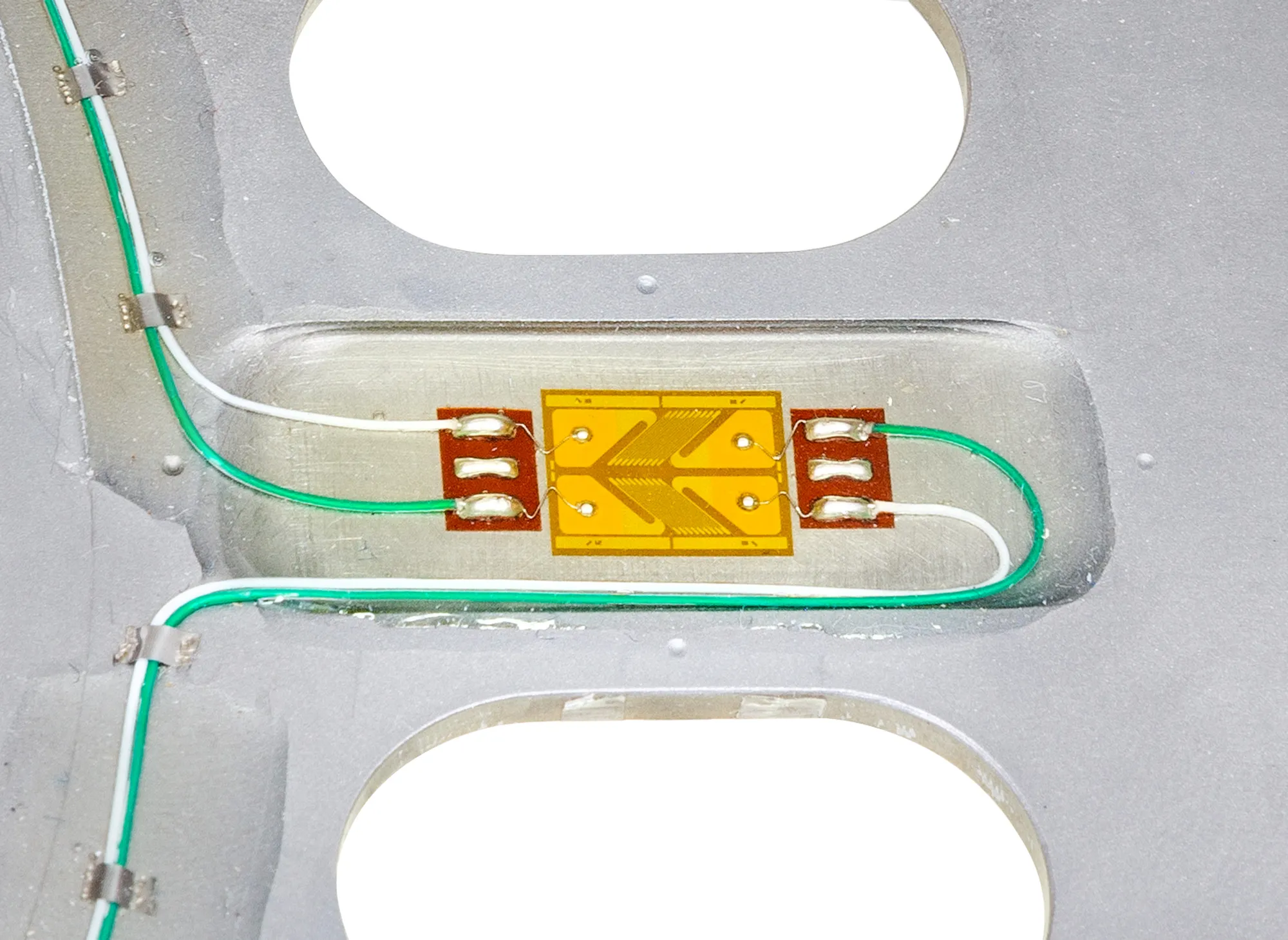 Engine Crankshaft measurements Torque, bending and strain on your own crankshaft with the engine running, in the vehicle or on the dyno.
 -
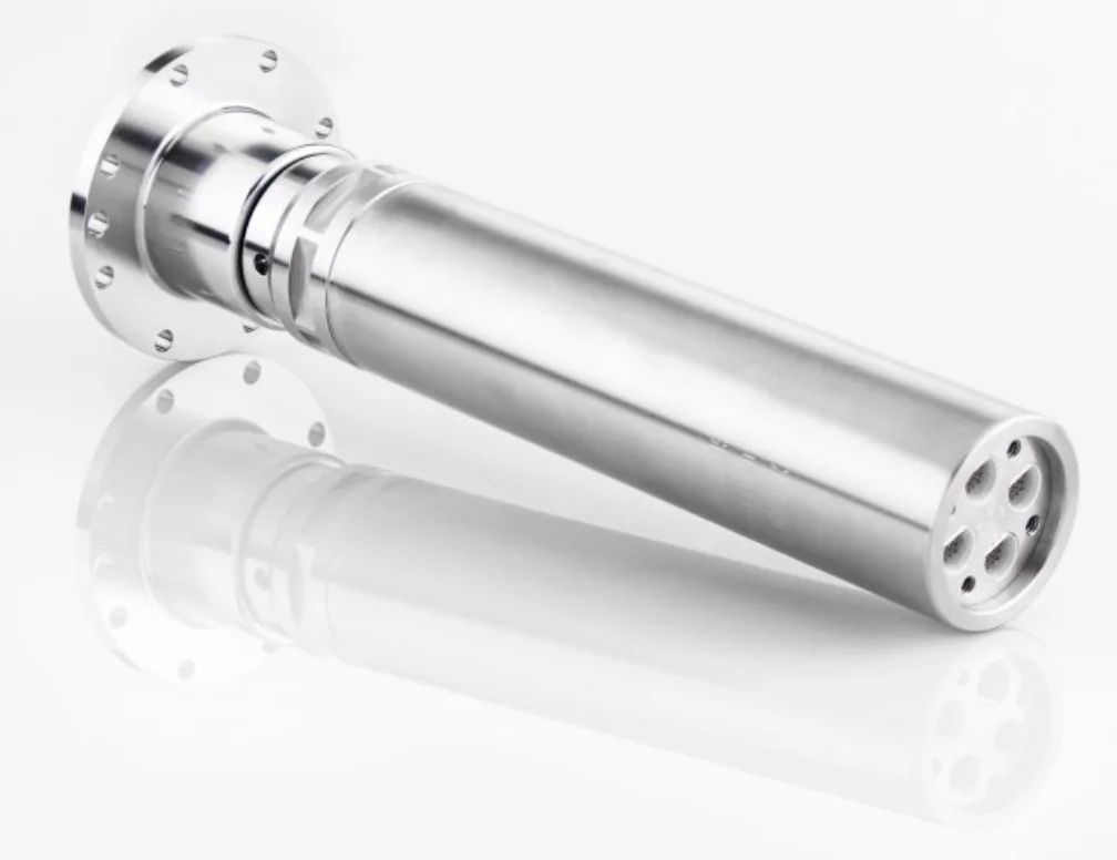 Turbines Fan and turbine blades Strain and temperature from many points on the blades, recorded together while the rotor turns.
In the same family
A question on this product?
Describe the measurement. An application engineer answers.
More details to give? Use the full contact form.