
LW-MC-3.5K wheel force transducer
Six-axis wheel force transducer for motorcycles, 15.5 kN radial and 5.3 kN lateral, with telemetry, induction power and encoder built into the transducer.
- 15.5 kN
- Fx, Fz capacity
- 5.3 kN
- Fy capacity
- 1.6 / 3.4 kN·m
- Moment capacity
- < 1 % FS
- Non-linearity
- OutputsFx Fy Fz · Mx My Mz
- Also measuredX and Z acceleration (X, Y, Z on the LW50 and LW55) · wheel speed and angle
- Signal outputanalog · CAN · Ethernet · CAN FD and EtherCAT on the CT3
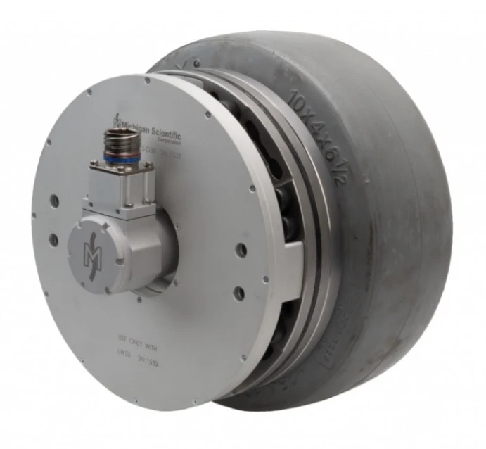
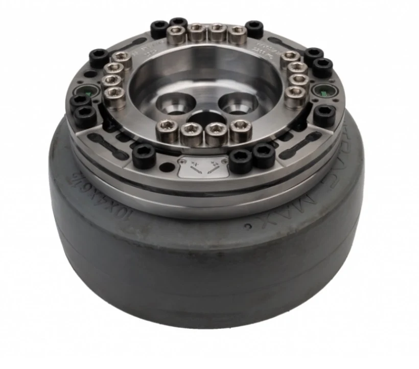
LW-MC-3.5K: motorcycle wheel force transducer, 15.5 kN
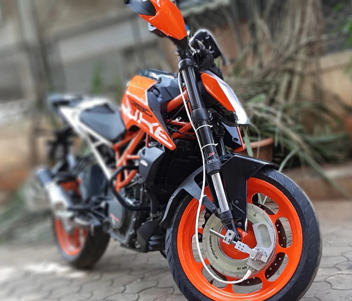
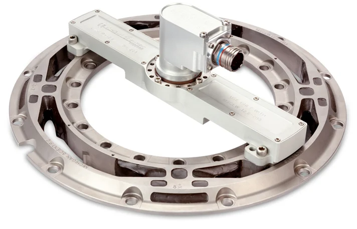
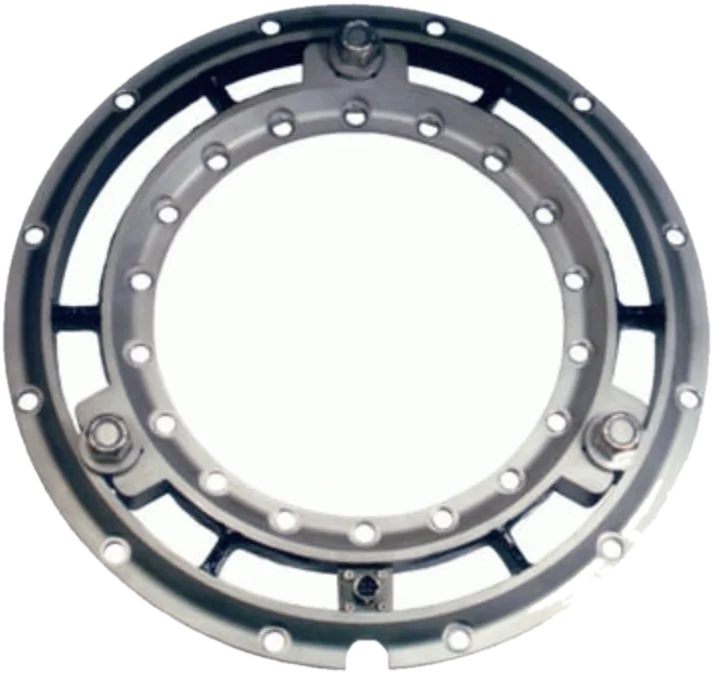
The LW-MC-3.5K measures all the wheel forces and moments on a motorcycle: vertical, lateral and longitudinal forces, and camber, steer and torque moments. Its 4-arm strain gage bridges are rated 15.5 kN (3,500 lb) on Fx and Fz, 5.3 kN (1,200 lb) on Fy, 1.6 kN·m on Mx and Mz and 3.4 kN·m on My. The telemetry and induction power electronics and the magnetic encoder wheel are packaged into the transducer, 2.25 kg with them. It is weatherproof and temperature compensated, operates from −40 to 125 °C, resolves the wheel angle to 0.25° and adapts to 11 in and larger wheels.
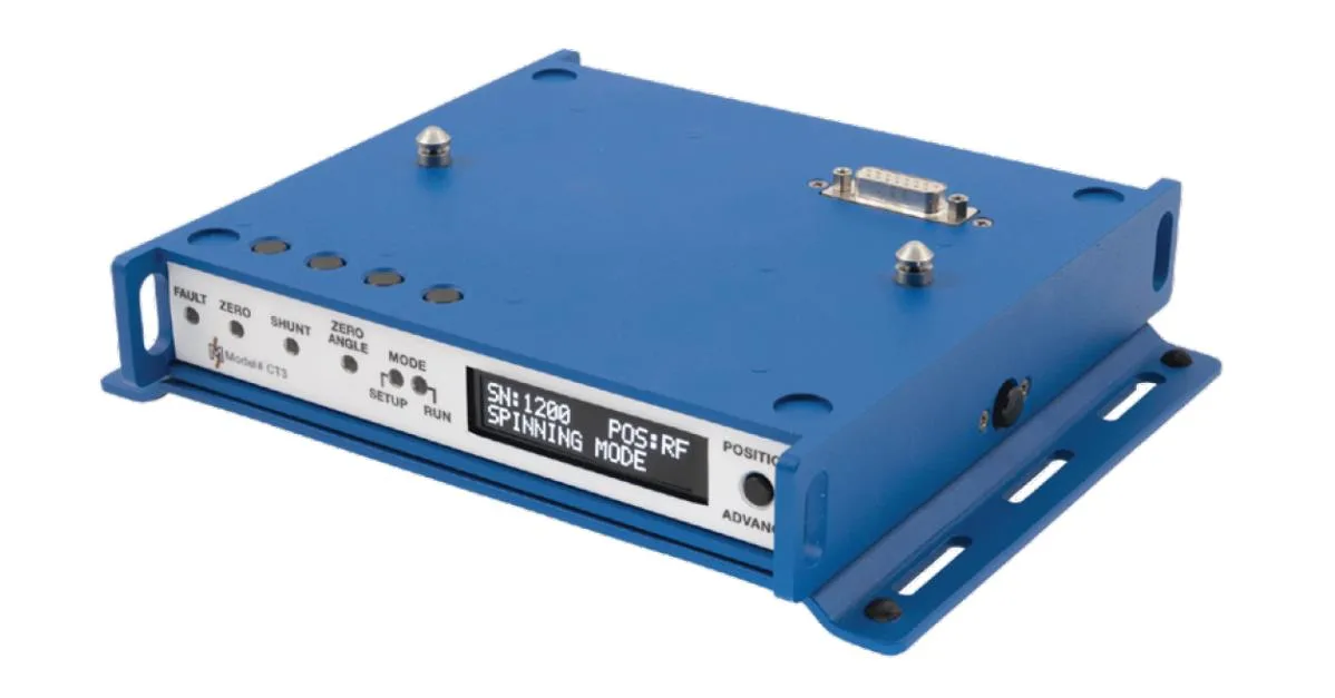
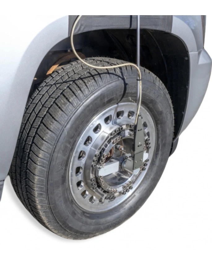
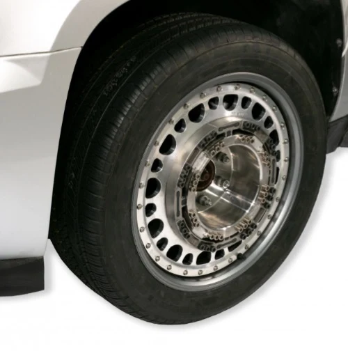
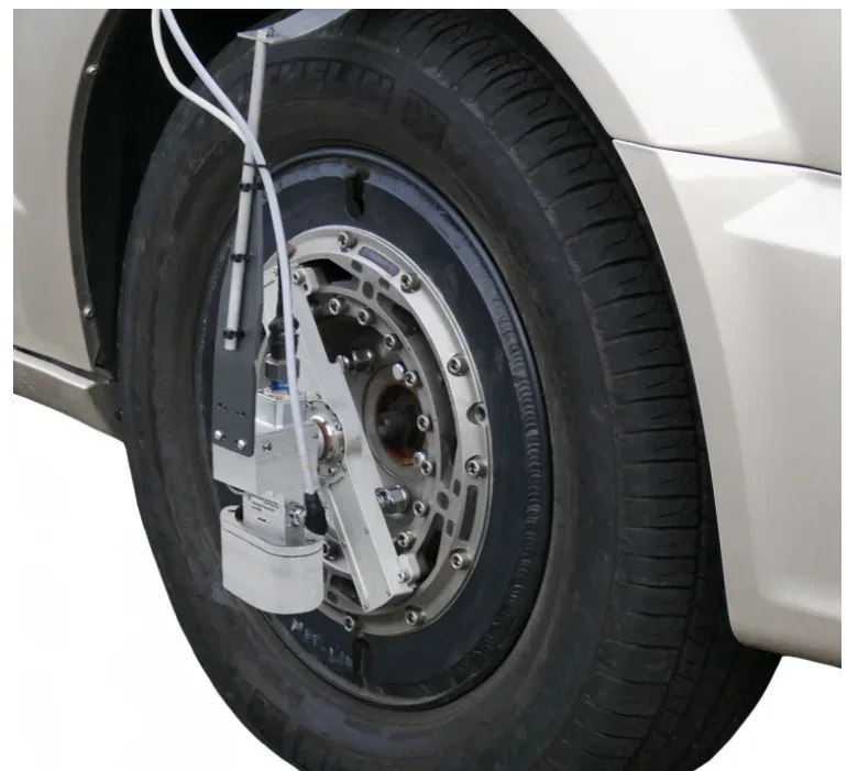
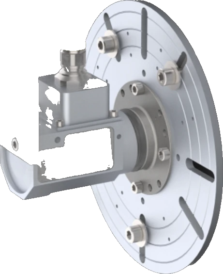
The transducer pilots into the modified wheel with sixteen M8 × 1.25 screws, and the hub adapter, made to the offset of the production wheel, pilots into it with eighteen more, all torqued crosswise to 20 N·m (15 lb·ft). An adjustable bracket holds the telemetry stator outboard of the transducer, aligned with a spacer. The CT3 box, powered at 9 to 36 V DC, reads the telemetry stator, zeroes the transducer, checks the shunt calibration and gives the loads in motorcycle coordinates.
It is the LW series model for motorcycles. On the same motorcycle, it gives the forces and moments at the wheel while a handlebar torque transducer measures the input of the rider.
Specifications
| Measured quantities | Fx · Fy · Fz · Mx · My · Mz |
|---|---|
| Force capacity | Fx 15.5 · Fy 5.3 · Fz 15.5 kN |
| Moment capacity | Mx 1 600 · My 3 400 · Mz 1 600 N·m |
| Non-linearity | ≤ 1 % FS |
| Hysteresis | ≤ 0.5 % FS |
| Crosstalk | ≤ 1 % FS (after compensation) |
| Angle resolution | 0.25° |
| Axes | 6 |
| Sensing principle | Strain gage (4-arm bridges) |
| Output | Analog voltage · CAN · CAN FD · Ethernet · EtherCAT (CT3; EtherCAT with an add-on module) |
| Bandwidth | 0.2 kHz (< −0.1 dB; 500 Hz at < −1.0 dB) |
| Sample rate | 2.2 kHz |
| Resolution | 16 bit |
| Signal transmission | Telemetry |
| Supply voltage | 10 to 36 V (about 2.0 A at 13.5 V DC) |
| Power source | Induction |
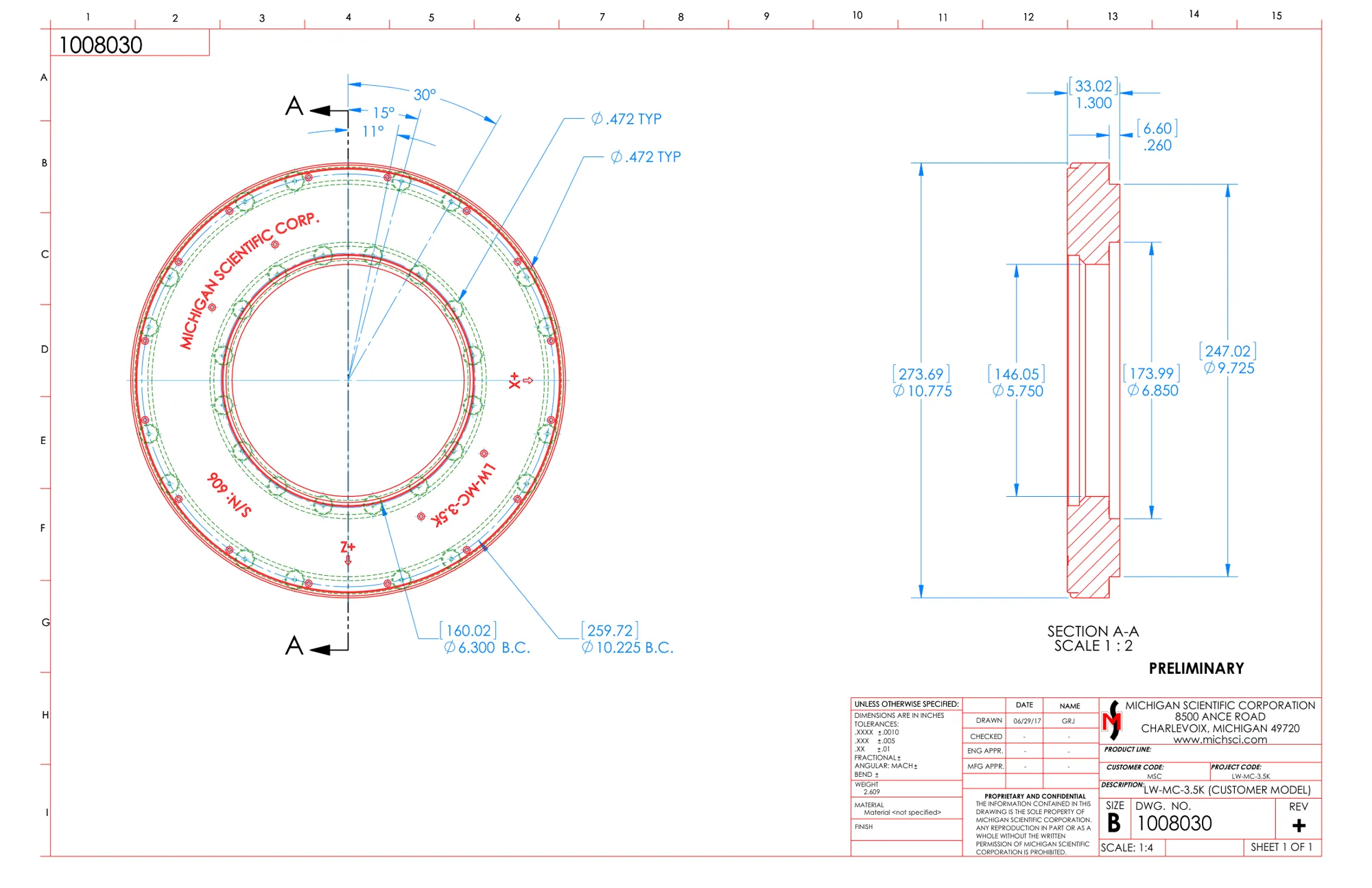
| Shaft diameter | 146.05 mm (center bore) |
| Bolt circle | 160.02 mm |
| Rim bolt circle | 259.72 mm |
| Dimensions | Ø 273.69 × 33.02 mm |
| Weight | 2.25 kg (with telemetry electronics) |
| Operating temperature | −40 to 125 °C |
| Operating temperature, stationary electronics | −25 to 75 °C (CT3) |
| Interface box | CT3 |
| Vehicles | Motorcycles |
| Rim size | 11 in (and larger) |
Request a quote
Unusual bolt pattern, motorsport hub, agricultural wheel: we build it around your wheel.
Resources
Datasheets and manuals
Related applications
-
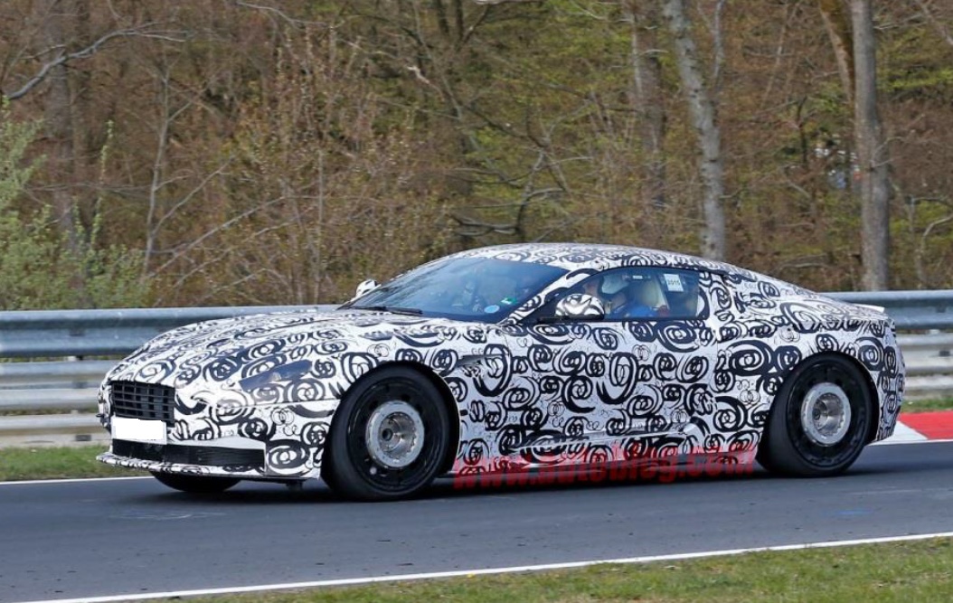 Durability Wheel loads on the road Three forces and three moments at each wheel, recorded while the vehicle is driven.
-
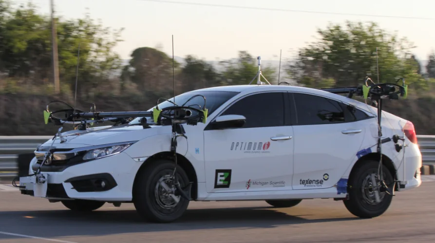 Dynamics Vehicle dynamics The forces and moments at each wheel while the vehicle brakes, turns and changes lane.
-
 Dynamics Side slip angle Side slip angle read without contact by an optical sensor, on a wheel or on the vehicle body.
-
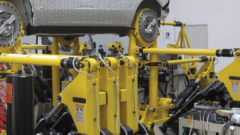 Test rig Road simulators The loads measured at the wheel on the road, and the proof that the simulator reproduces them.
If a six-axis wheel is not what you need
- Torque only TW series wheel torque transducers
Drive and brake torque My at the wheel, 237 N·m to 81 kN·m.
- Signals from the series wheel Wheel instrumentation system
Strain gages, thermocouples and wheel speed, on the wheel the vehicle already has.
- Force on a part, not a wheel TR3D-B three-axis load cells
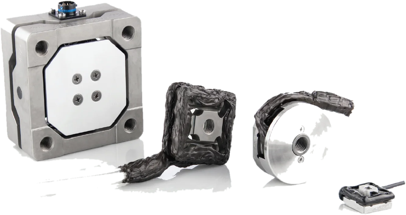
Three orthogonal forces from 1.1 to 71 kN per axis.
A question on this product?
Vehicle, wheel size, expected loads. An application engineer answers.
More details to give? Use the full contact form.