
LW700 6-axis wheel force transducer, 700 kN, 275 kN·m
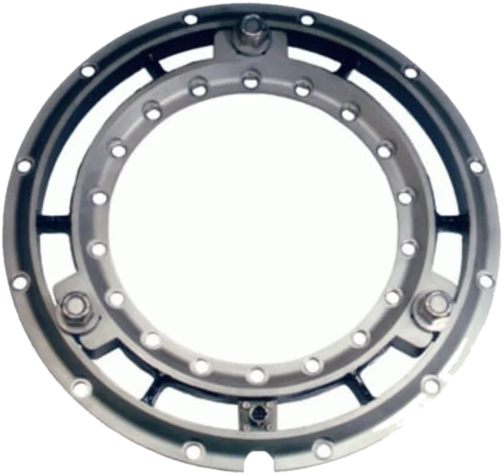
Six-axis wheel force transducer for standard hubs with a 425 mm PCD, 700 kN per force and 275 kN·m per moment, sealed to IP67, with slip ring or telemetry.
- 700 kN
- Fx, Fz capacity
- 700 kN
- Fy capacity
- 275 kN·m
- Moment capacity
- ≤ 0.5 % FS
- Non-linearity
- OutputsFx Fy Fz · Mx My Mz
- Also measuredX and Z acceleration · wheel position and speed
- Signal outputCAN FD · CAN 2.0 · Ethernet on the CT3; analog and EtherCAT with optional modules
- Signal transmissionslip ring or telemetry
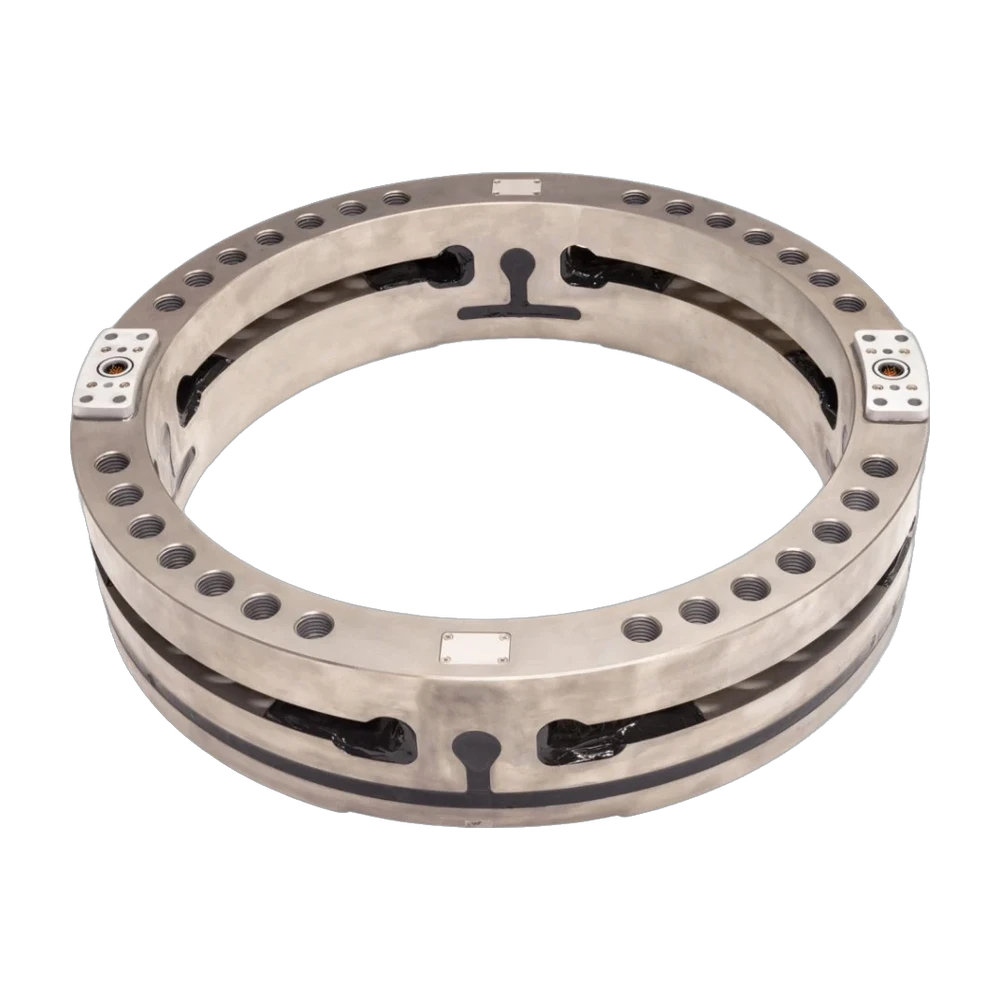
LW700: wheel force transducer, 700 kN
The LW700 measures all the wheel forces and moments: vertical, lateral and longitudinal forces up to 700 kN each (Fx, Fy, Fz), and camber, steer and torque moments of 275 kN·m each. The maximum recommended static load is 23,800 kg. Non-linearity and hysteresis are 0.5 % of full scale or less, and cross-axis sensitivity after correction 0.2 %. Of robust IP67 design, the transducer weighs 64.5 kg and fits standard hubs with a 425 mm pitch circle diameter. Its ± 100 g accelerometers give X and Z accelerations, and an encoder gives wheel position and speed.
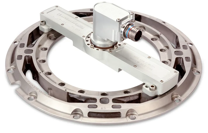
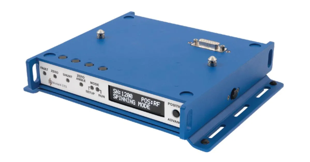
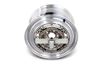
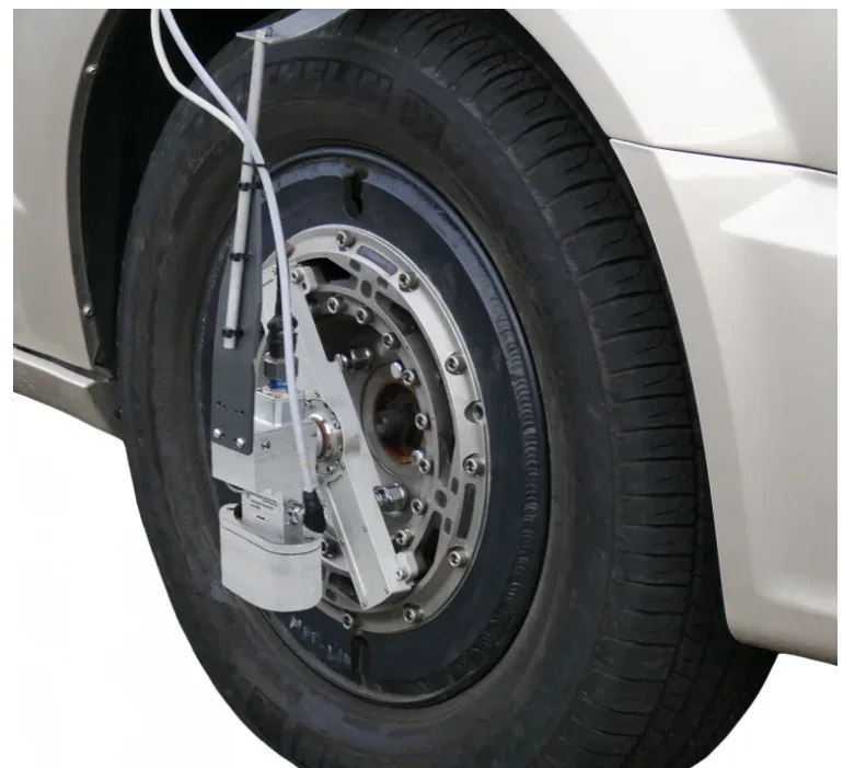
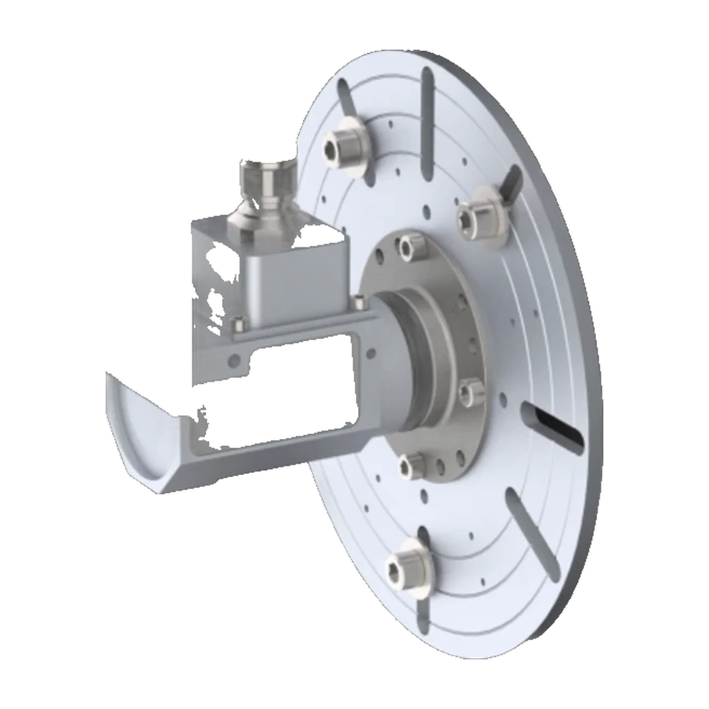
In spinning use, the signals leave through an outboard slip ring, with the amplifier package mounted onto the transducer, or through inboard telemetry, whose stator, mounted close to the rotating telemetry ring, holds the receiver, the encoder pick-ups and the induction coil; the CT3 box then also supplies the induction power. The CT3 performs coordinate transformation and crosstalk, offset and polarity correction, with zero, shunt calibration check and zero angle functions; its embedded web page, reached over USB, sets up the system and moves the measurement origin.
Its robust IP67 design suits the harshest track and off-road measurements; in non-spinning applications, the LW700 is used to monitor and control laboratory test rigs.
Specifications
| Measured quantities | Fx · Fy · Fz · Mx · My · Mz |
|---|---|
| Force capacity | Fx 700 · Fy 700 · Fz 700 kN |
| Moment capacity | Mx 275 000 · My 275 000 · Mz 275 000 N·m |
| Max static load | 23 800 kg |
| Non-linearity | ≤ 0.5 % FS |
| Hysteresis | ≤ 0.5 % FS |
| Crosstalk | ≤ 0.2 % FS (after correction) |
| Angle resolution | 0.17° |
| Axes | 6 |
| Sensing principle | Strain gage |
| Accelerometer range | 100 g |
| Output | Analog voltage · CAN · CAN FD · Ethernet |
| Signal transmission | Slip ring · Telemetry |
| Supply voltage | 10 to 36 V |
| Power source | External supply · Through the slip ring |
| Max speed | 2 000 rpm |
| Weight | 64.5 kg |
| Protection | IP67 |
| Interface box | CT3 |
| Vehicles | Heavy equipment · Construction equipment |
| Hub bolt pattern | 425 mm (standard hubs) |
Used with the LW700
What you add here goes into the same quote request.
-
Measure on a steered wheel
SAC stator angle corrector
Corrects the rotation angle signal in real time for the coordinate transformation, with no over-the-wheel bracket. Internal encoder accuracy ≤ 0.25°, IP67.
Slip ring versions, with the CT3 interface box.
Resources
Datasheets and manuals
Drawings
None for LW700.
CAD models
None for LW700.
Guides and notes
Related applications
-
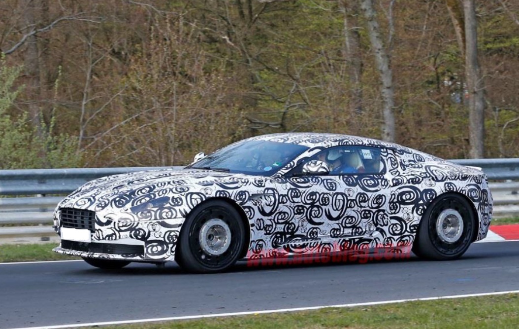 Durability Wheel loads on the road Three forces and three moments at each wheel, recorded while the vehicle is driven.
-
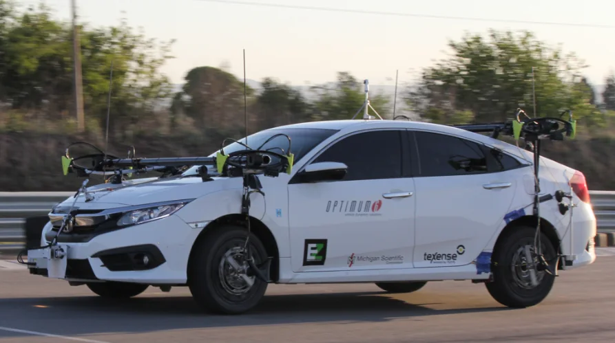 Dynamics Vehicle dynamics The forces and moments at each wheel while the vehicle brakes, turns and changes lane.
-
 Dynamics Side slip angle Side slip angle read without contact by an optical sensor, on a wheel or on the vehicle body.
-
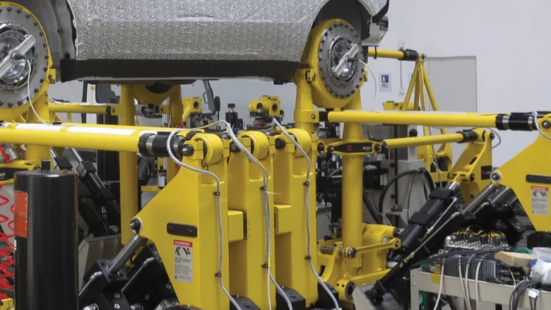 Test rig Road simulators The loads measured at the wheel on the road, and the proof that the simulator reproduces them.
If the LW700 is not the one
- Torque only Wheel torque transducers
Drive and brake torque at the wheel, while the vehicle is driven.
- Signals from the series wheel Wheel Instrumentation System
Strain gage and thermocouple signals off a rotating wheel, on the vehicle's own wheel, on track or off-road.
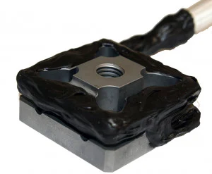
- Force on a part, not a wheel TR3D-B
Three perpendicular forces from a square body, down to 25.4 mm a side.
A question on this product?
Vehicle, wheel size, expected loads. An application engineer answers.
More details to give? Use the full contact form.