
LW-2T-60K-S wheel force transducer
Six-axis wheel force transducer for class 8 trucks and large off-road vehicles, the lower-capacity of the two heavy-duty models: 300 kN radial, 150 kN lateral, 81 kN·m.
- 300 kN
- Fx, Fz capacity
- 150 kN
- Fy capacity
- 81 kN·m
- Moment capacity
- ≤ 1 % FS
- Non-linearity
- OutputsFx Fy Fz · Mx My Mz
- Also measuredX and Z acceleration · wheel speed and angle
- Signal outputanalog · CAN · Ethernet · CAN FD and optional EtherCAT
- Signal transmissionswappable slip ring or telemetry
LW-2T-60K-S: heavy-duty wheel force transducer, 300 kN
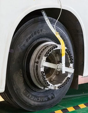
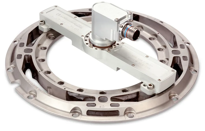
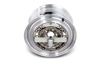
The LW-2T-60K-S is the lower-capacity of the two Michigan Scientific heavy-duty wheel force transducers for class 8 trucks and large off-road vehicles: 67,400 lbf (300 kN) radial (Fx, Fz), 33,700 lbf (150 kN) lateral at the tire patch (Fy) and 60,000 lbf·ft (81 kN·m) on the camber, steer and torque moments. One transducer measures the combined loads of a dual wheel set or a single tire, on 20 in and larger wheels and 285 mm or 335 mm hub bolt patterns. For higher loads, the LW-2T-100K-S takes 445 kN radial in the same outline.
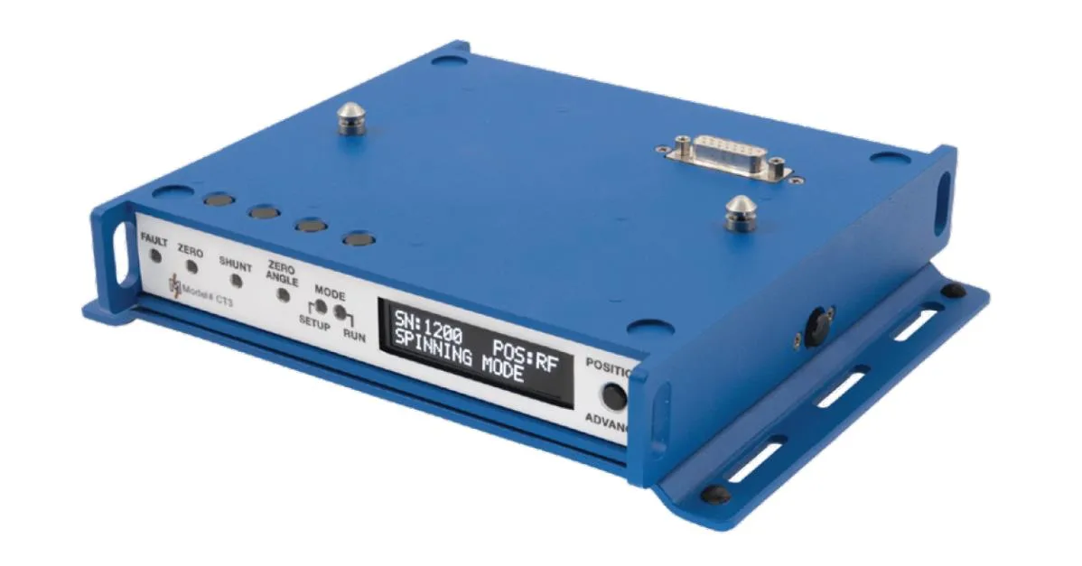
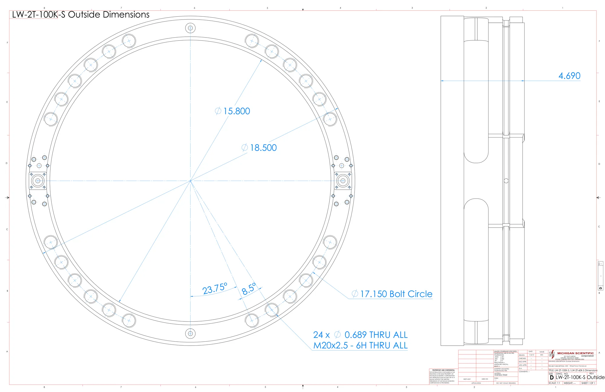
Twenty-four Ø 17.5 mm through holes and M20 × 2.5 threads lie on a Ø 435.6 mm bolt circle. On dual wheels, both rim adapters bolt onto the transducer with the same M20 bolts, then the hub adapter with twenty-four more, tightened with a torque multiplier; stand-offs carry the amplifier bar. A magnetic restraint holds the slip ring stator vertical, or the stator angle correction device on steered wheels. The CT3 interface box, powered at 9 to 36 V DC, runs the shunt calibration check and the zero.
The CT3 User Interface Box performs the real-time coordinate transformation and crosstalk correction, leaving less than 1 % of full scale, and outputs CAN FD, CAN 2.0 and Ethernet, with EtherCAT and analog outputs as options; an embedded webpage, reached over USB, configures the system. The transducer is weatherproof and is used on-road and off-road in all conditions, and to monitor and control laboratory tests.
Specifications
| Measured quantities | Fx · Fy · Fz · Mx · My · Mz |
|---|---|
| Force capacity | Fx 300 · Fy 150 · Fz 300 kN |
| Moment capacity | Mx 81 000 · My 81 000 · Mz 81 000 N·m |
| Max static load | 6 125 kg |
| Non-linearity | ≤ 1 % FS |
| Hysteresis | ≤ 0.5 % FS |
| Crosstalk | ≤ 1 % FS (after correction) |
| Angle resolution | 0.17° |
| Axes | 6 |
| Sensing principle | Strain gage (4-arm bridges) |
| Accelerometer range | 55 g |
| Output | Analog voltage · CAN · CAN FD |
| Signal transmission | Slip ring · Telemetry |
| Shaft diameter | 401.3 mm (center bore) |
| Mounting fasteners | 24 × Ø 17.5 mm (through holes, and M20 × 2.5 threads) |
| Bolt circle | 435.6 mm |
| Dimensions | Ø 469.9 × 119.1 mm |
| Material | Stainless steel |
| Operating temperature | −40 to 125 °C |
| Interface box | CT3 |
| Vehicles | Class 8 trucks · Off-road vehicles · Off-road equipment · Heavy equipment |
| Hub bolt pattern | 285 · 335 mm |
| Rim size | 20 in (and larger, single or dual) |
Used with the LW-2T-60K-S
What you add here goes into the same quote request.
-
Measure on a steered wheel
SAC stator angle corrector
Corrects the rotation angle signal in real time for the coordinate transformation, with no over-the-wheel bracket. Internal encoder accuracy ≤ 0.25°, IP67.
Slip ring versions, with the CT3 interface box.
Resources
Datasheets and manuals
CAD models
Guides and notes
Related applications
-
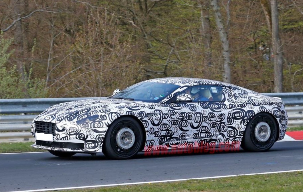 Durability Wheel loads on the road Three forces and three moments at each wheel, recorded while the vehicle is driven.
-
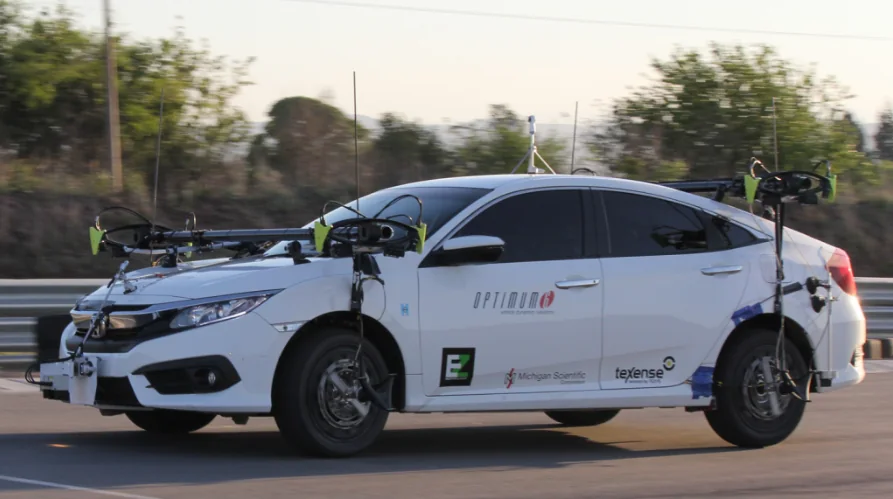 Dynamics Vehicle dynamics The forces and moments at each wheel while the vehicle brakes, turns and changes lane.
-
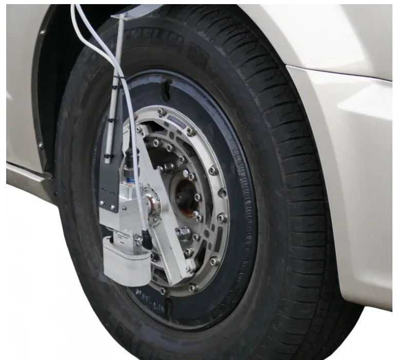 Dynamics Side slip angle Side slip angle read without contact by an optical sensor, on a wheel or on the vehicle body.
-
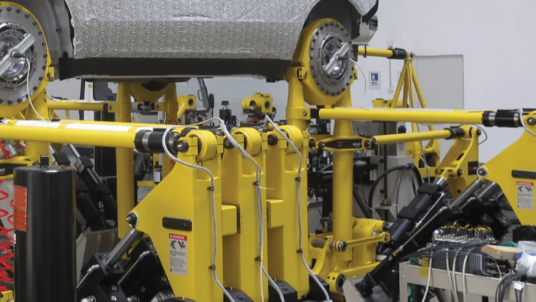 Test rig Road simulators The loads measured at the wheel on the road, and the proof that the simulator reproduces them.
If the LW-2T-60K-S is not the one
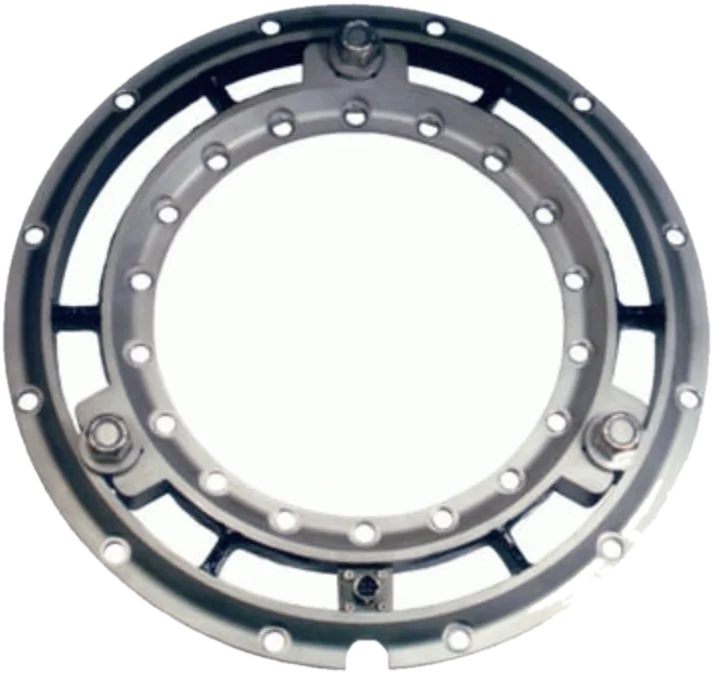
- Torque only Wheel torque transducers
Drive and brake torque at the wheel, while the vehicle is driven.
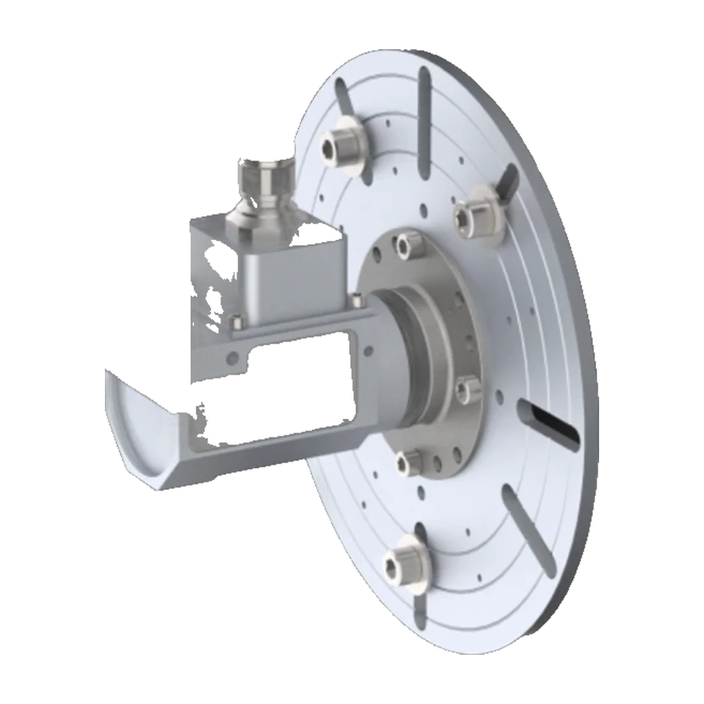
- Signals from the series wheel Wheel Instrumentation System
Strain gage and thermocouple signals off a rotating wheel, on the vehicle's own wheel, on track or off-road.
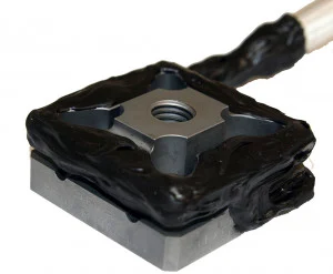
- Force on a part, not a wheel TR3D-B
Three perpendicular forces from a square body, down to 25.4 mm a side.
A question on this product?
Vehicle, wheel size, expected loads. An application engineer answers.
More details to give? Use the full contact form.