
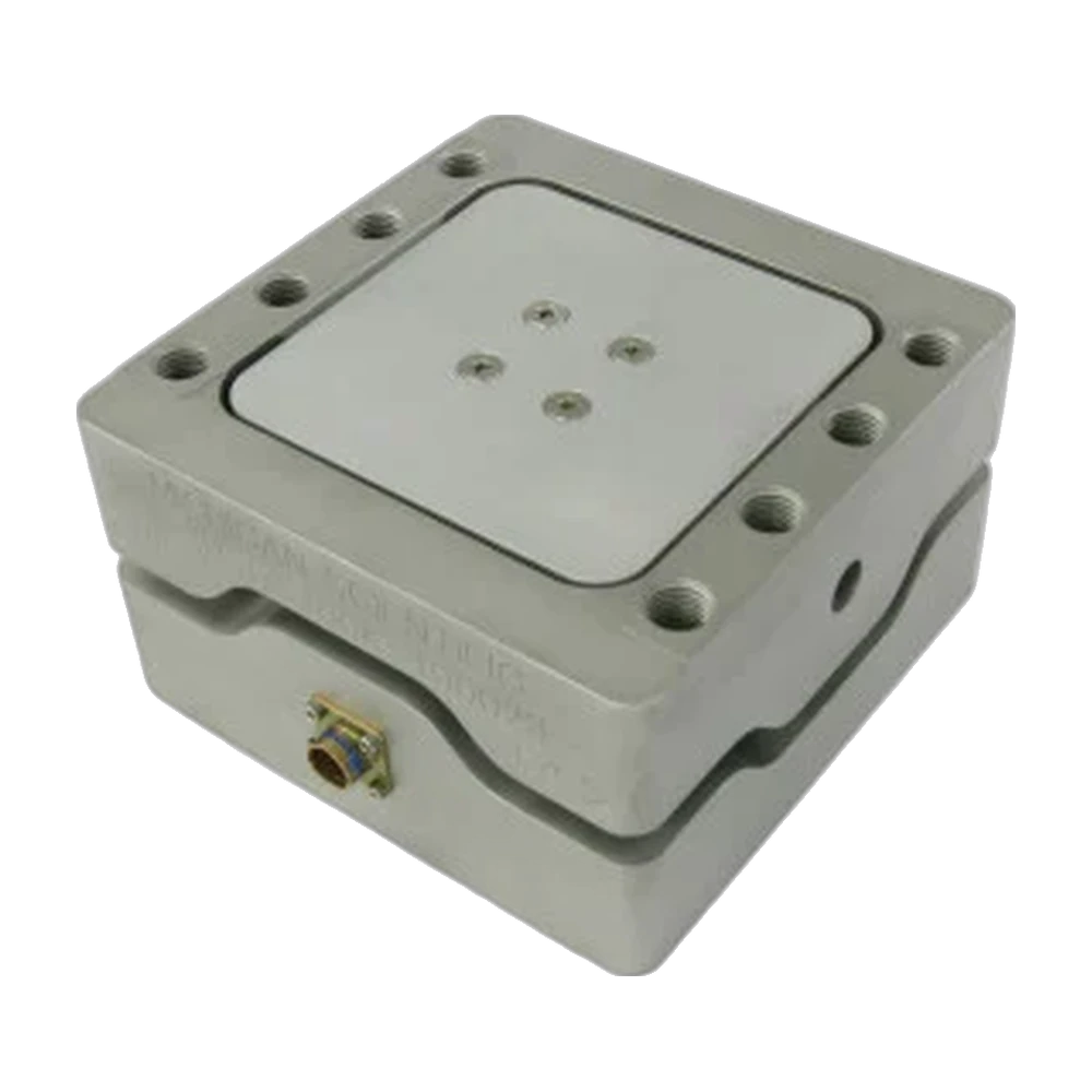
TR3D-D square three-axis load cell
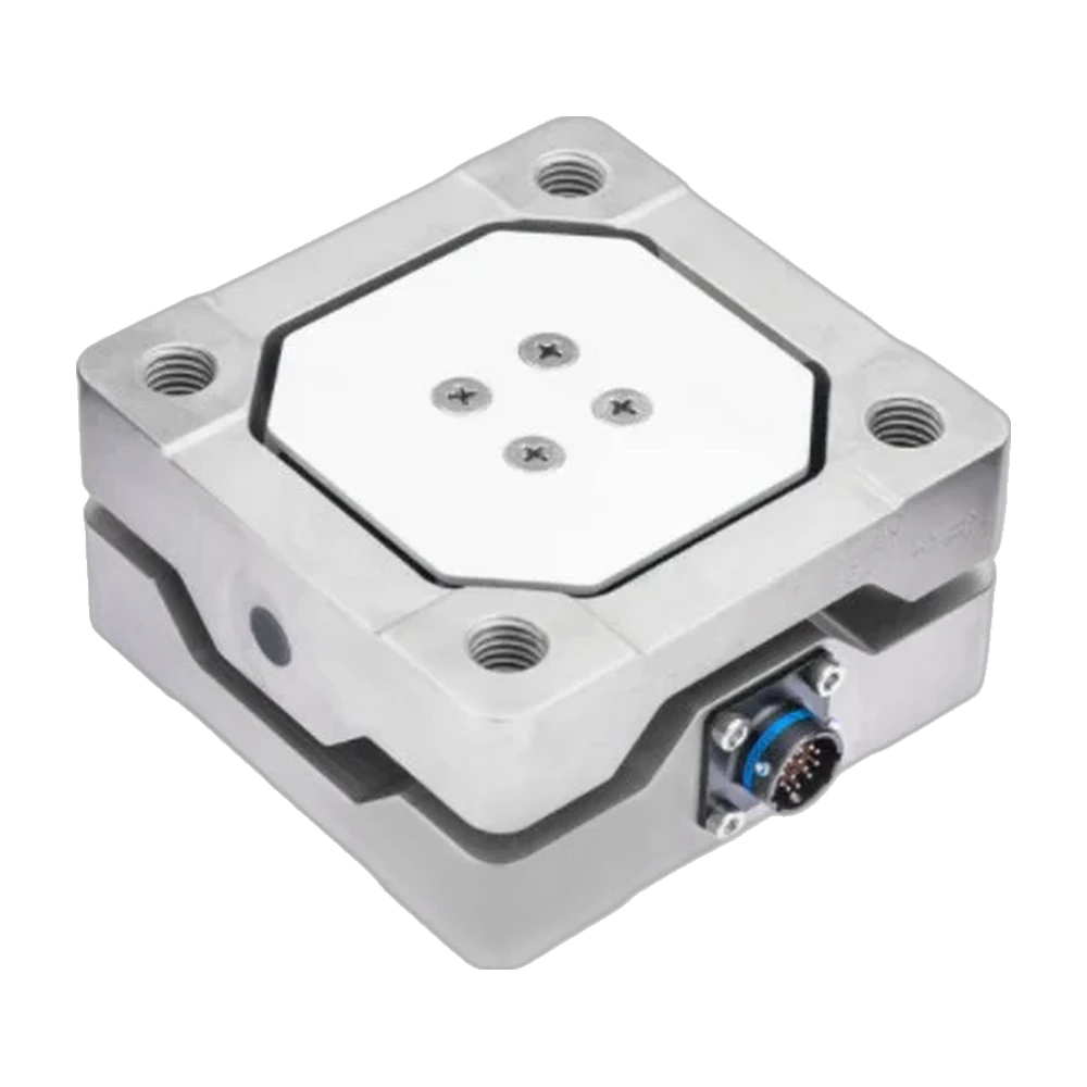
Square three-axis load cell for forces up to 222 kN per axis, in a 177.8 × 177.8 × 101.6 mm stainless steel body with a weatherproof connector.
Square three-axis load cell for forces up to 444 kN per axis, in a 177.8 × 177.8 × 101.6 mm stainless steel body with a weatherproof connector.
- 222 kN
- Measuring range per axis
- 19 000 N·m
- Max moment per axis
- 1.50 mV/V
- Output
- 177.8 × 177.8 × 101.6 mm
- Dimensions
- 444 kN
- Measuring range per axis
- 20 300 N·m
- Max moment per axis
- 1.25 mV/V
- Output
- 177.8 × 177.8 × 101.6 mm
- Dimensions
- Included3.05 m cable · ISO/IEC 17025 calibration report
- Included3.05 m cable · ISO/IEC 17025 calibration report
TR3D-D-50K: square three-axis load cell, 222 kN per axis
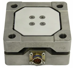
The TR3D-D-50K is a square three-axis load cell. Three four-arm strain gage bridges, one per axis, measure the forces in X, Y and Z up to 222 kN (50,000 lbf) each; the maximum moment is 19.0 kN·m per axis. The stainless steel body measures 177.8 × 177.8 × 101.6 mm and weighs 17.5 kg; it is weatherproof sealed, with a weatherproof connector. The full-scale output is 1.50 mV/V nominal at up to 10 V excitation, DC or AC rms, with hysteresis below 0.5 % of full scale. It is temperature compensated from 24 to 93 °C and usable from −40 to 149 °C.
The top and base have identical mounting surfaces, each with eight M16 × 2 threads, so the cell bolts between two flanges. Each bridge is powered separately on its own four leads (P+, S+, S−, P−), at the end of a 3.05 m shielded cable; connectors and the cable length can be specified at order. Positive outputs result when the top moves relative to the base in the marked directions. Each channel is calibrated to full scale, with an ISO/IEC 17025 calibration report that records cross-talk.
The TR3D-D is built for field data acquisition and laboratory testing. Several TR3D load cells are used in arrays between two stiff fixtures when the combined load exceeds the capacity of a single cell.
TR3D-D-100K: square three-axis load cell, 444 kN per axis
The TR3D-D-100K is a square three-axis load cell. Three four-arm strain gage bridges, one per axis, measure the forces in X, Y and Z up to 444 kN (100,000 lbf) each; the maximum moment is 20.3 kN·m per axis. The stainless steel body measures 177.8 × 177.8 × 101.6 mm and weighs 17.5 kg; it is weatherproof sealed, with a weatherproof connector. The full-scale output is 1.25 mV/V nominal at up to 10 V excitation, DC or AC rms, with hysteresis below 0.5 % of full scale. It is temperature compensated from 24 to 93 °C and usable from −40 to 149 °C.
The top and base have identical mounting surfaces, each with eight M16 × 2 threads, so the cell bolts between two flanges. Each bridge is powered separately on its own four leads (P+, S+, S−, P−), at the end of a 3.05 m shielded cable; connectors and the cable length can be specified at order. Positive outputs result when the top moves relative to the base in the marked directions. Each channel is calibrated to full scale, with an ISO/IEC 17025 calibration report that records cross-talk.
The TR3D-D is built for field data acquisition and laboratory testing. Several TR3D load cells are used in arrays between two stiff fixtures when the combined load exceeds the capacity of a single cell.
Specifications
| Measured quantities | Fx · Fy · Fz |
|---|---|
| Force capacity | Fx 222 · Fy 222 · Fz 222 kN |
| Moment capacity | 19 000 N·m (max per axis) |
| Non-linearity | Fx ≤ 1 · Fy ≤ 1 · Fz ≤ 2 % FS |
| Hysteresis | ≤ 0.5 % FS |
| Axes | 3 (orthogonal) |
| Sensing principle | Strain gage (3 four-arm bridges) |
| Zero shift over temperature | ≤ 0.2 % FS |
| Rated output | 1.5 mV/V |
| Excitation voltage | 10 V (max, DC or AC rms) |
| Mounting fasteners | 8 × M16 × 2 (on top, 8 on the base) |
| Dimensions | 177.8 × 177.8 × 101.6 mm |
| Weight | 17.5 kg |
| Material | Stainless steel |
| Operating temperature | −40 to 149 °C |
| Compensated temperature | 24 to 93 °C |
| Connections | Cable (shielded, open-ended leads) |
| Cable length | 3.05 m |
| Measured quantities | Fx · Fy · Fz |
|---|---|
| Force capacity | Fx 444 · Fy 444 · Fz 444 kN |
| Moment capacity | 20 300 N·m (max per axis) |
| Non-linearity | Fx ≤ 1 · Fy ≤ 1 · Fz ≤ 2 % FS |
| Hysteresis | ≤ 0.5 % FS |
| Axes | 3 (orthogonal) |
| Sensing principle | Strain gage (3 four-arm bridges) |
| Zero shift over temperature | ≤ 0.2 % FS |
| Rated output | 1.25 mV/V |
| Excitation voltage | 10 V (max, DC or AC rms) |
| Mounting fasteners | 8 × M16 × 2 (on top, 8 on the base) |
| Dimensions | 177.8 × 177.8 × 101.6 mm |
| Weight | 17.5 kg |
| Material | Stainless steel |
| Operating temperature | −40 to 149 °C |
| Compensated temperature | 24 to 93 °C |
| Connections | Cable (shielded, open-ended leads) |
| Cable length | 3.05 m |
Connectors and cable length can be specified when ordering.
Used with the TR3D-D
What you add here goes into the same quote request.
-
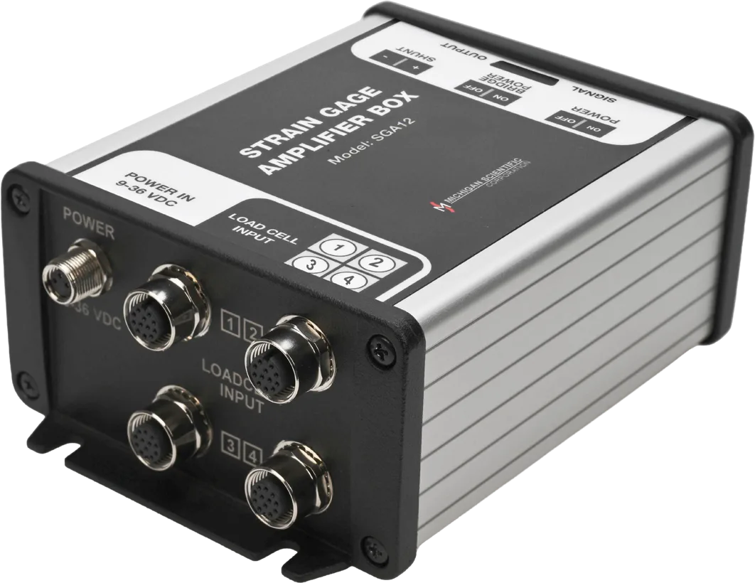
Read the three axes as ± 10 V
SGA3, the three-channel model of the SGA series
± 5 V bridge excitation, a ± 10 V output per axis and shunt calibration from a switch on the box.
One SGA3 per load cell.
-
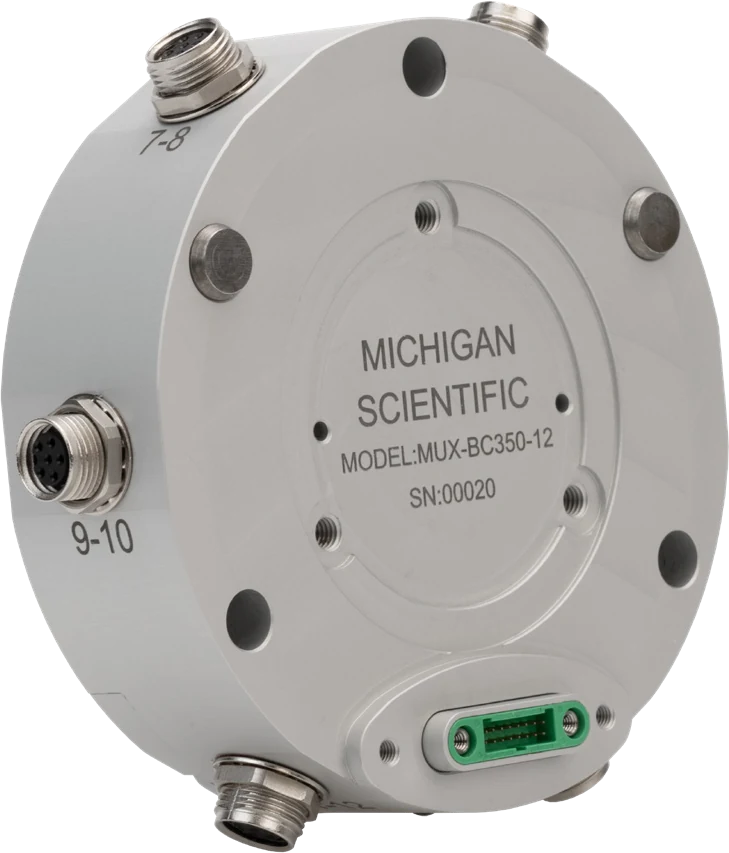
Log every axis on one CAN bus
MUX-FB-12, the full-bridge module of the MUX-12 series
Twelve full-bridge inputs, one CAN 2.0 or CAN FD output up to 8 ksps, integrated shunt resistors for calibration.
Twelve channels per module; up to four modules stack for 48 synchronized channels.
Resources
Datasheets and manuals
Drawings
None for TR3D-D-50K.
CAD models
None for TR3D-D-50K.
Datasheets and manuals
Drawings
None for TR3D-D-100K.
CAD models
Related applications
-
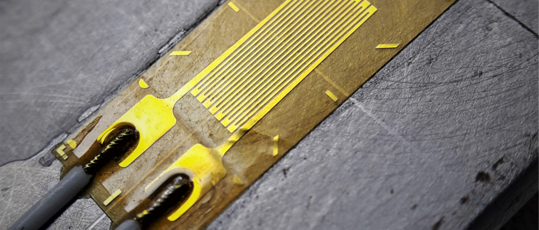 Lifting Crane load monitoring The force at each point of a crane's rope and rigging, so that no part is loaded beyond its capacity.
-
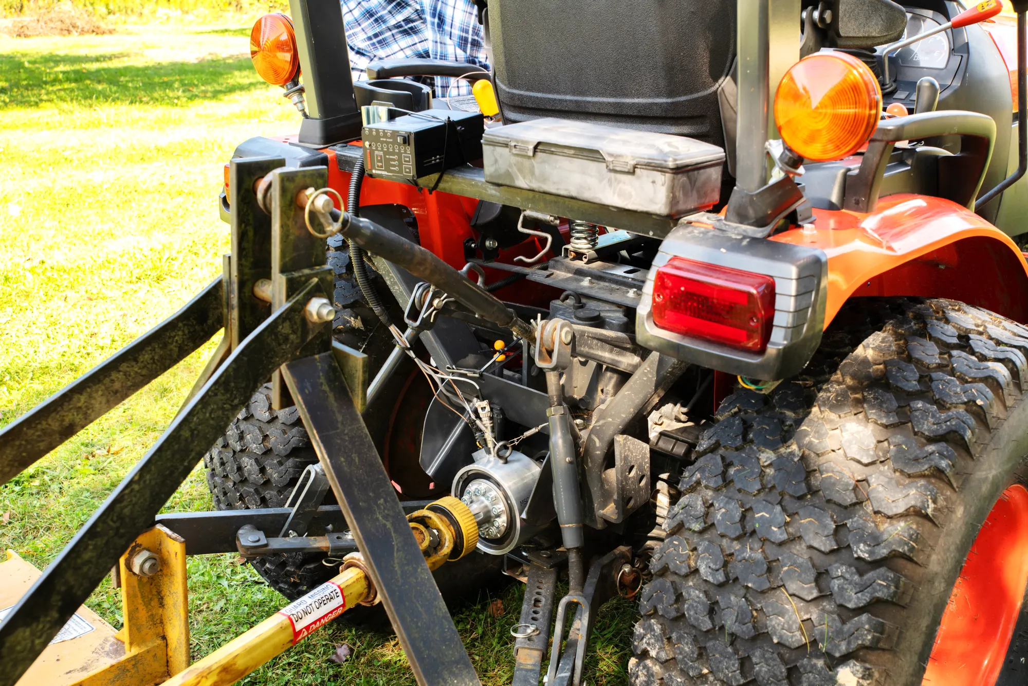 Agriculture PTO torque and power The torque and speed that the tractor delivers to the implement, measured during real field work.
-
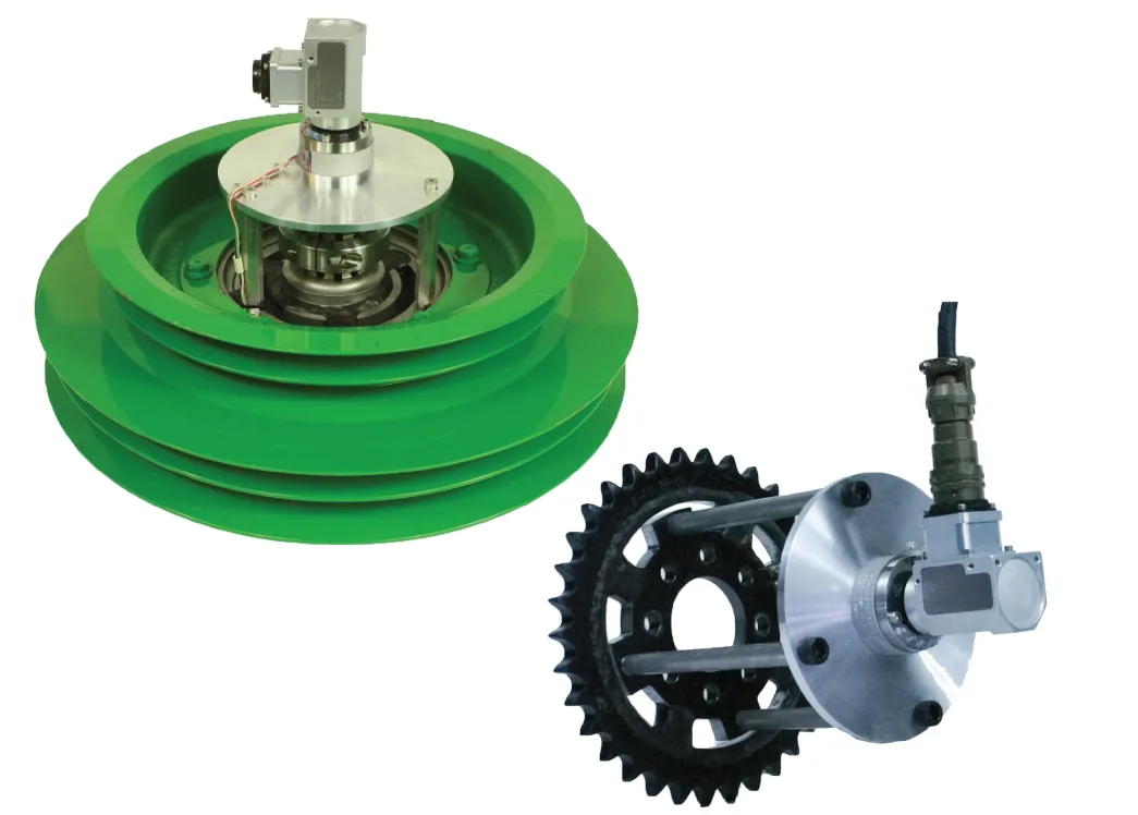 Agriculture Combine harvester gearbox Torque, speed and temperature on the pulleys, gears and gearboxes of a combine, to find power losses.
-
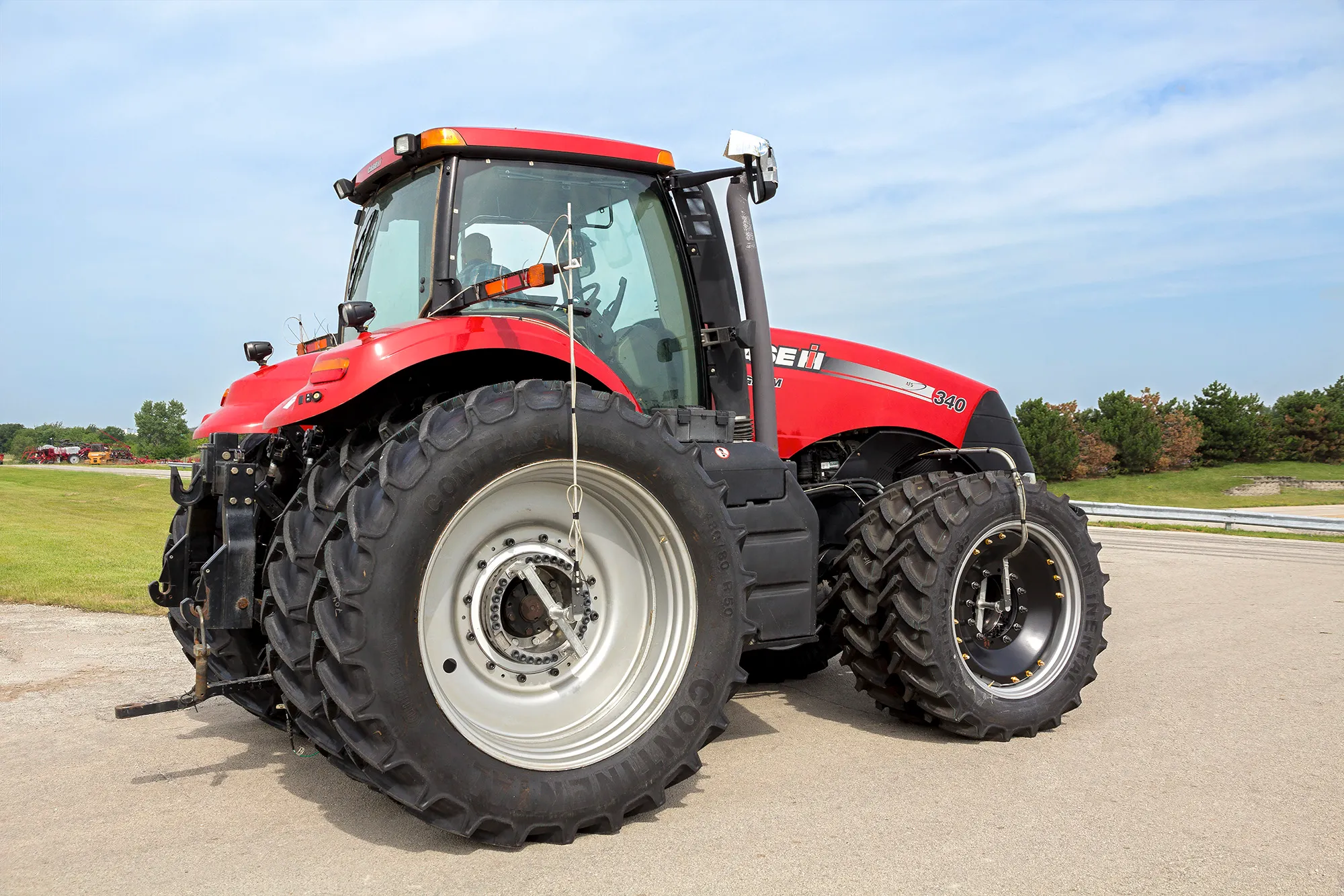 Agriculture Agricultural machinery Wheel loads, wheel torque, PTO power and forces on working parts, measured on the machine at work.
Other bodies, more axes
A question on this product?
Load range per axis, mounting, test type. An application engineer answers.
More details to give? Use the full contact form.