
MUX-12 series twelve-channel analog to CAN module
Twelve-channel quarter-bridge strain gage amplifier: 350 Ω bridge completion, 4.5 V excitation and 16-bit digitization onto one CAN 2.0 or CAN FD bus, up to 8 ksps.
Twelve-channel full-bridge strain gage amplifier: 4.5 V excitation, conditioning and 16-bit digitization onto one CAN 2.0 or CAN FD bus, up to 8 ksps.
Twelve-channel thermocouple module, type K, J or T, with cold junction compensation and linearization, onto one CAN bus, up to 1 ksps.
Twelve-channel amplifier for high-level sensors such as accelerometers and string pots: 4.8 V sensor power, conditioning and 16-bit digitization onto one CAN 2.0 or CAN FD bus, up to 8 ksps.
Twelve-channel module for PT100 resistance temperature detectors, onto one CAN bus, up to 8 ksps.
Model MUX-BC350-12
- 12
- Quarter-bridge channels, 350 Ω
- 8 ksps
- Max output rate, CAN FD
- ± 36 mV
- Input range
- Ø 86 × 25.4 mm
- Housing
- 12
- Full-bridge channels
- 8 ksps
- Max output rate, CAN FD
- ± 36 mV
- Input range
- Ø 86 × 25.4 mm
- Housing
- 12
- Thermocouple channels
- 1 ksps
- Max output rate
- K, J, T
- Thermocouple types
- 12
- High-level channels
- 8 ksps
- Max output rate, CAN FD
- ± 2.2 V
- Input range
- 4.8 V
- Sensor power
- 12
- PT100 RTD channels
- 8 ksps
- Max output rate
- OutputCAN 2.0 / CAN FD
- Max output rate8 ksps, CAN FD; 2 ksps, CAN 2.0
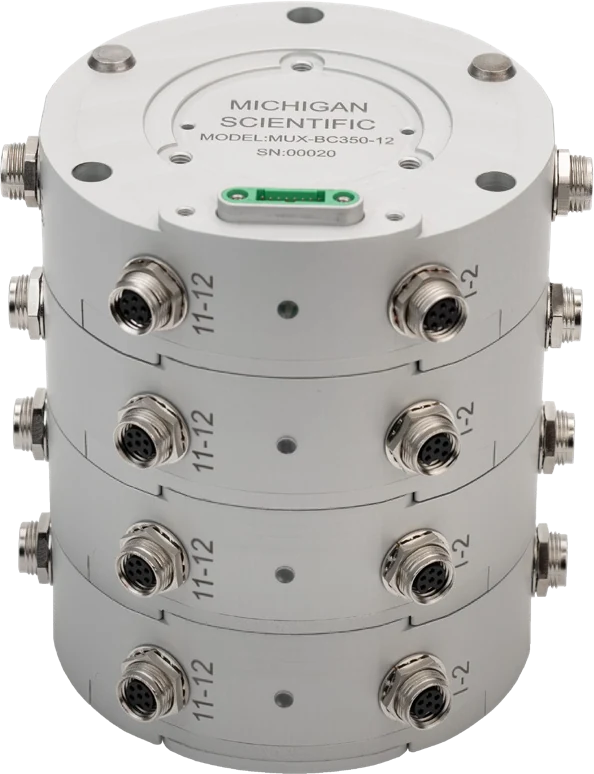
- StackingUp to 4 modules, 48 synchronized channels
- ConfigurationSoftware, per channel
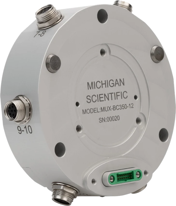
MUX-BC350-12: twelve quarter-bridge gages onto one CAN bus
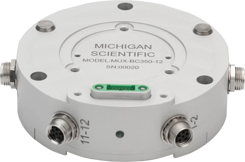
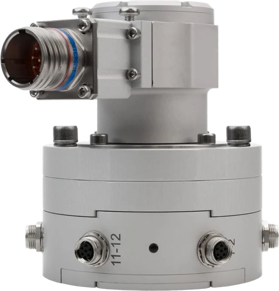
The MUX-BC350-12 takes twelve 350 Ω quarter-bridge strain gages in 3-wire hook-up, two per M8 6-pin connector. It completes each bridge with a 0.01 % resistor, excites it at 4.5 V ratiometric and digitizes it at 16 bits, on a ±36 mV input range with gain and zero balance set by software; positive and negative shunt calibration runs through an integrated 100 kΩ resistor. Output: CAN 2.0 up to 2 ksps, CAN FD up to 8 ksps on all twelve channels, 1.6 kHz at −3 dB. Supply 10 to 20 V DC; −40 to 85 °C; IP67 with the stacking connectors.
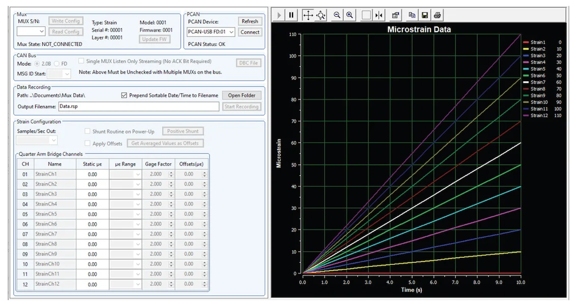
The module ships with its sensor cables, a setup cable for power and CAN, and the MUX Tool software for Windows. Over a PEAK-System USB-to-CAN adapter, the software configures each channel, gage factor included, records one module to a PC and generates the DBC file for a data recorder. Up to four modules stack, without cables between them, for 48 synchronized channels.
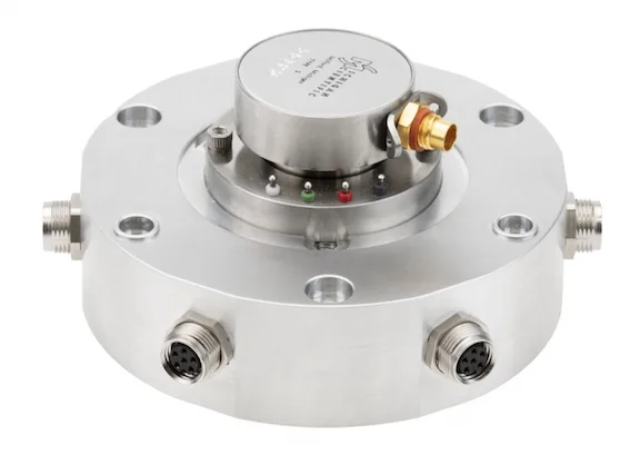
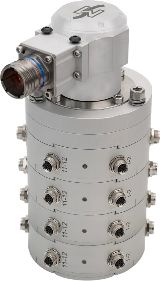
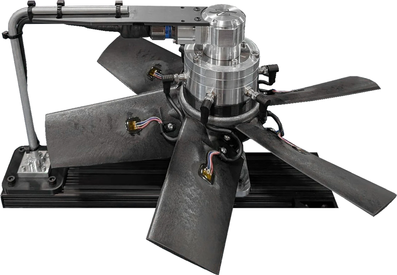
On a rotating part, the module takes a slip ring on its top face, such as the S4, or the SR10AW/WFT and its 1024 ppr encoder through the MUX-ENC-ADA adapter layer. On a fixed part, the MUX-CON-ADA-NS adapter layer takes the power and data cable.
MUX-FB-12: twelve full-bridge transducers onto one CAN bus
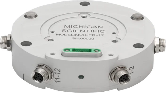
The MUX-FB-12 takes twelve full-bridge strain gage transducers in 4-wire connection, two per M8 8-pin connector. Each channel has its own amplifier: 4.5 V ratiometric excitation, ±36 mV input range with gain and bridge balance set by software, 16-bit digitization, and positive and negative shunt calibration through an integrated 100 kΩ resistor. Output: CAN 2.0 up to 2 ksps, CAN FD up to 8 ksps on all twelve channels, 1.6 kHz at −3 dB. Supply 10 to 36 V DC; −40 to 85 °C; IP67 with the stacking connectors.
The module ships with its sensor cables, a setup cable for power and CAN, and the MUX Tool software for Windows. Over a PEAK-System USB-to-CAN adapter, the software configures each channel, records one module to a PC and generates the DBC file for a data recorder. Up to four modules stack, without cables between them, for 48 synchronized channels.
On a rotating part, the SR10AW/WFT slip ring and its 1024 ppr encoder mount on the stack through the MUX-ENC-ADA adapter layer; encoder position and speed come out with the module data. On a fixed part, the MUX-CON-ADA-NS adapter layer takes the power and data cable.
MUX-TC-12: twelve thermocouples onto one CAN bus
The MUX-TC-12 takes twelve thermocouples of type K, J or T, with integrated cold junction compensation and linearization, at an output rate up to 1 ksps. Each module provides excitation where needed, conditioning and digitization, and delivers the twelve channels on one CAN 2.0 or CAN FD bus. Each channel is configured independently in the supplied software, which records to a PC; shunt verification is integrated, and up to four modules stack for 48 synchronized channels.
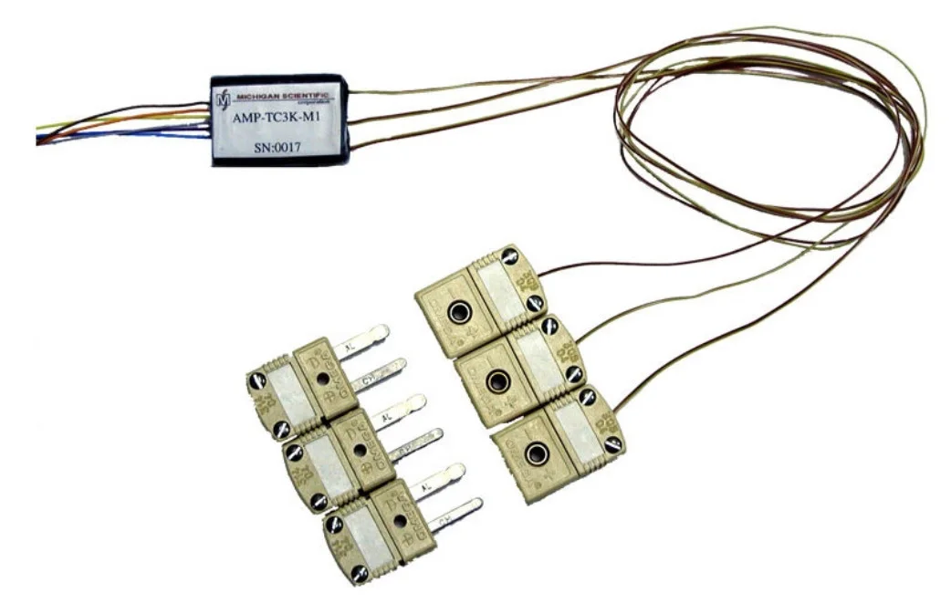
On a rotating part, the module works with any four-circuit Michigan Scientific slip ring, which then carries only power and CAN. For a few thermocouple channels amplified on the rotor, see choosing a thermocouple amplifier.
MUX-HL-12: twelve high-level sensors onto one CAN bus
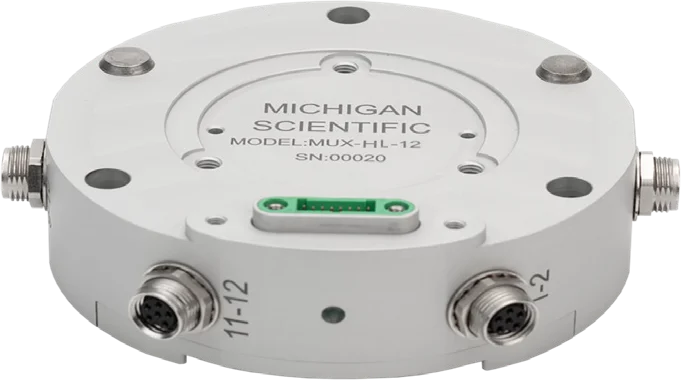
The MUX-HL-12 takes twelve high-level sensors in 3-wire connection, power, signal and ground, two per M8 6-pin connector. It powers each sensor at 4.8 V ratiometric, up to 13 mA, and digitizes a ±2.2 V input at 16 bits, with 0.1 % accuracy at 25 °C. Each channel is scaled by its sensitivity or a two-point calibration, proportional to excitation for ratiometric sensors, and zeroed by software. Output: CAN 2.0 up to 2 ksps, CAN FD up to 8 ksps, 1.6 kHz at −3 dB. Supply 10 to 36 V DC; −40 to 85 °C; IP67 with the stacking connectors.
The module ships with a power and CAN cable, a PEAK-System USB-to-CAN FD adapter and the MUX Tool software for Windows, which configures each channel, records one module to a PC and generates the DBC file for a data recorder. Up to four modules stack for 48 synchronized channels.
On a rotating part, the SR10AW/WFT slip ring and its 1024 ppr encoder mount on the stack through the MUX-ENC-ADA adapter layer; encoder position and speed come out with the module data.
MUX-RTD100-12: twelve PT100 RTDs onto one CAN bus
The MUX-RTD100-12 takes twelve 100 Ω resistance temperature detectors (PT100), with an output rate up to 8 ksps. Each module provides excitation where needed, conditioning and digitization, and delivers the twelve channels on one CAN 2.0 or CAN FD bus. Each channel is configured independently in the supplied software, which records to a PC; shunt verification is integrated, and up to four modules stack for 48 synchronized channels.
On a rotating part, the module works with any four-circuit Michigan Scientific slip ring, which then carries only power and CAN. For thermocouples instead, see the MUX-TC-12.
Specifications
| Channels | 12 (per module, stackable to 48 with four modules) |
|---|---|
| Input | Strain gage bridge (quarter bridge, 3-wire hook-up; input range ±36 mV) |
| Output | CAN · CAN FD |
| Bandwidth | 1.6 kHz (−3 dB; 0.5 kHz at −0.1 dB, 4 or 8 ksps output rate) |
| Sample rate | 8 kHz (12 channels, CAN FD at 4 Mbit/s; 2 kHz on CAN 2.0) |
| Noise, referred to input | ≤ 0.25 µV (p-p, 0.1 to 10 Hz; density about 12 nV/√Hz) |
| Gain setting | Software (per channel; PC software included for configuration and data recording) |
| Shunt calibration | Positive · Negative · Software (integrated; also at power-up) |
| Shunt resistor | 100 kΩ (up to 10 MΩ emulated) |
| Gain accuracy | ≤ 0.2 % |
| Gain temperature coefficient | ≤ 0.004 %/°C |
| Input offset | ≤ 50 µV |
| Offset drift | ≤ 0.5 µV/°C |
| Shunt accuracy | ≤ 0.075 % |
| Supply voltage | 10 to 20 V |
| Excitation voltage | 4.5 V (ratiometric) |
| Bridge resistance | 350 Ω |
| Power consumption | 2 W (typical, at 12 V DC, no sensors) |
| Excitation current limit | 13 mA |
| Bridge completion | Yes (350 Ω, 0.01 %, 2 ppm/°C) |
| Galvanic isolation | 200 V (channel to CAN and channel to power; not a safety isolation for high-voltage applications) |
| Dimensions | Ø 86 × 25.4 mm (housing) |
| Weight | 300 g (approx.) |
| Operating temperature | −40 to 85 °C |
| Protection | IP67 (with stacking connectors) |
| Connections | Connector (inputs: 6 × M8 6-pin, two gages each; power and CAN through the stacking connector) |
| Channels | 12 (per module, stackable to 48 with four modules) |
|---|---|
| Input | Strain gage bridge (full bridge, 4-wire; input range ±36 mV) |
| Output | CAN · CAN FD |
| Bandwidth | 1.6 kHz (−3 dB; 0.5 kHz at −0.1 dB, 4 or 8 ksps output rate) |
| Sample rate | 8 kHz (12 channels, CAN FD at 4 Mbit/s; 2 kHz on CAN 2.0) |
| Noise, referred to input | ≤ 0.25 µV (p-p, 0.1 to 10 Hz; density about 12 nV/√Hz) |
| Gain setting | Software (per channel; PC software included for configuration and data recording) |
| Shunt calibration | Positive · Negative · Software (integrated; also at power-up) |
| Shunt resistor | 100 kΩ (up to 10 MΩ emulated) |
| Gain accuracy | ≤ 0.2 % |
| Gain temperature coefficient | ≤ 0.004 %/°C |
| Input offset | ≤ 50 µV |
| Offset drift | ≤ 0.5 µV/°C |
| Shunt accuracy | ≤ 0.075 % |
| Supply voltage | 10 to 36 V |
| Excitation voltage | 4.5 V (ratiometric) |
| Power consumption | 2 W (typical, at 12 V DC with 12 bridges) |
| Excitation current limit | 13 mA |
| Galvanic isolation | 200 V (channel to CAN and channel to power; not a safety isolation for high-voltage applications) |
| Dimensions | Ø 86 × 25.4 mm (housing) |
| Weight | 300 g (approx.) |
| Operating temperature | −40 to 85 °C |
| Protection | IP67 (with stacking connectors) |
| Connections | Connector (inputs: 6 × M8 8-pin, two bridges each; power and CAN through the stacking connector) |
| Channels | 12 (per module, stackable to 48 with four modules) |
|---|---|
| Input | Thermocouple |
| Thermocouple types | J · K · T |
| Output | CAN · CAN FD |
| Sample rate | 1 kHz |
| Gain setting | Software (per channel; PC software included for configuration and data recording) |
| Cold junction compensation | Yes (integrated, with linearization) |
| Channels | 12 (per module, stackable to 48 with four modules) |
|---|---|
| Input | Voltage (high level, 3-wire; input range ±2.2 V) |
| Output | CAN · CAN FD |
| Bandwidth | 1.6 kHz (−3 dB; 0.5 kHz at −0.1 dB, 4 or 8 ksps output rate) |
| Sample rate | 8 kHz (CAN FD at 4 Mbit/s; 2 kHz on CAN 2.0, 12 channels) |
| Noise, referred to input | ≤ 12 µV (rms, 1.6 kHz bandwidth) |
| Gain setting | Software (per channel; PC software included for configuration and data recording) |
| Input offset | ≤ 50 µV |
| Offset drift | ≤ 0.5 µV/°C |
| Supply voltage | 10 to 36 V |
| Excitation voltage | 4.8 V (sensor power, ratiometric) |
| Power consumption | 1 W (typical, at 12 V DC, no sensors) |
| Excitation current limit | 13 mA |
| Galvanic isolation | 200 V (channel to CAN and channel to power; not a safety isolation for high-voltage applications) |
| Dimensions | Ø 86 × 25.4 mm (housing) |
| Weight | 300 g (approx.) |
| Operating temperature | −40 to 85 °C |
| Protection | IP67 (with stacking connectors) |
| Connections | Connector (inputs: 6 × M8 6-pin, two sensors each; power and CAN through the stacking connector) |
| Channels | 12 (per module, stackable to 48 with four modules) |
|---|---|
| Input | RTD (PT100, 100 Ω) |
| Output | CAN · CAN FD |
| Sample rate | 8 kHz |
| Gain setting | Software (per channel; PC software included for configuration and data recording) |
Request a quote
Works with
- TR3D-AThree perpendicular forces from one round body, mounted on a single central thread.
- TR3D-BThree perpendicular forces from a square body, down to 25.4 mm a side.
- TR3D-CThree perpendicular forces in a rugged stainless steel body, the same bolt pattern on both faces.
- TR3D-DThree perpendicular forces up to 444 kN per axis, in a stainless steel body with a weatherproof connector.
- TR5D-B-5KSquare five-axis load cell in sealed stainless steel: Fx, Fy, Fz to 22 kN and two bending moments, Mx and My, to 815 N·m, 33.34 mm high.
- TR6D-CSquare six-axis load cells, sealed, with identical top and base bolt patterns: Fx, Fy, Fz, Mx, My and Mz, 71 to 178 kN and 1.4 to 9.5 kN·m.
- TR6D-FLow-profile six-axis load cells in sealed stainless steel: Fx, Fy, Fz, Mx, My and Mz, 12.5 to 45 kN and 370 N·m to 3.4 kN·m, 24 to 40 mm high.
Resources
Datasheets and manuals
Drawings
None for MUX-BC350-12.
CAD models
None for MUX-BC350-12.
Datasheets and manuals
Drawings
None for MUX-FB-12.
CAD models
None for MUX-FB-12.
Datasheets and manuals
Drawings
None for MUX-TC-12.
CAD models
None for MUX-TC-12.
Guides and notes
Datasheets and manuals
Drawings
None for MUX-HL-12.
CAD models
None for MUX-HL-12.
Datasheets and manuals
Drawings
None for MUX-RTD100-12.
CAD models
None for MUX-RTD100-12.
Guides and notes
A question on this product?
Describe the measurement. An application engineer answers.
More details to give? Use the full contact form.