
Model T3 3-channel end-of-shaft telemetry
End-of-shaft, induction-powered telemetry for three strain gage or thermocouple channels, in a bearing-free housing proven at 24 000 rpm, sampling up to 7 kHz per channel.
- 3
- Channels
- 24 000 rpm
- Proven speed
- 7 kHz
- Max sample rate per channel
- ±10 V
- Analog outputs
- MountingEnd of shaft
- InputsStrain gage or thermocouple
- Power supplyInduction, primary coil about 3 to 5 mm away
- Antenna distance1 to 3 m
Three channels on the end of the shaft
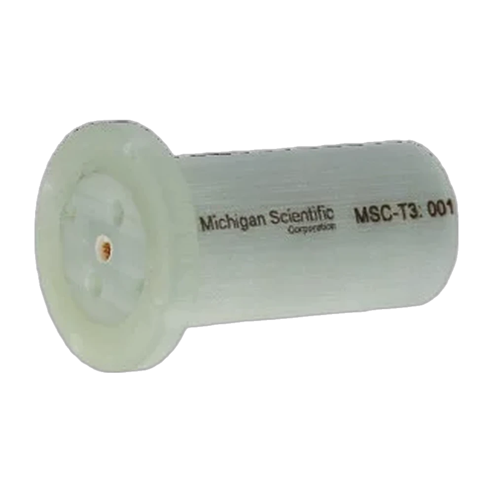
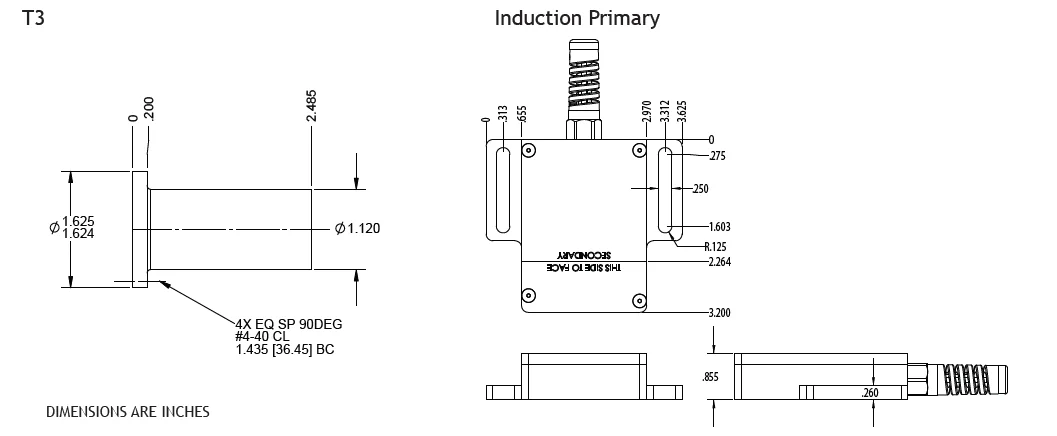
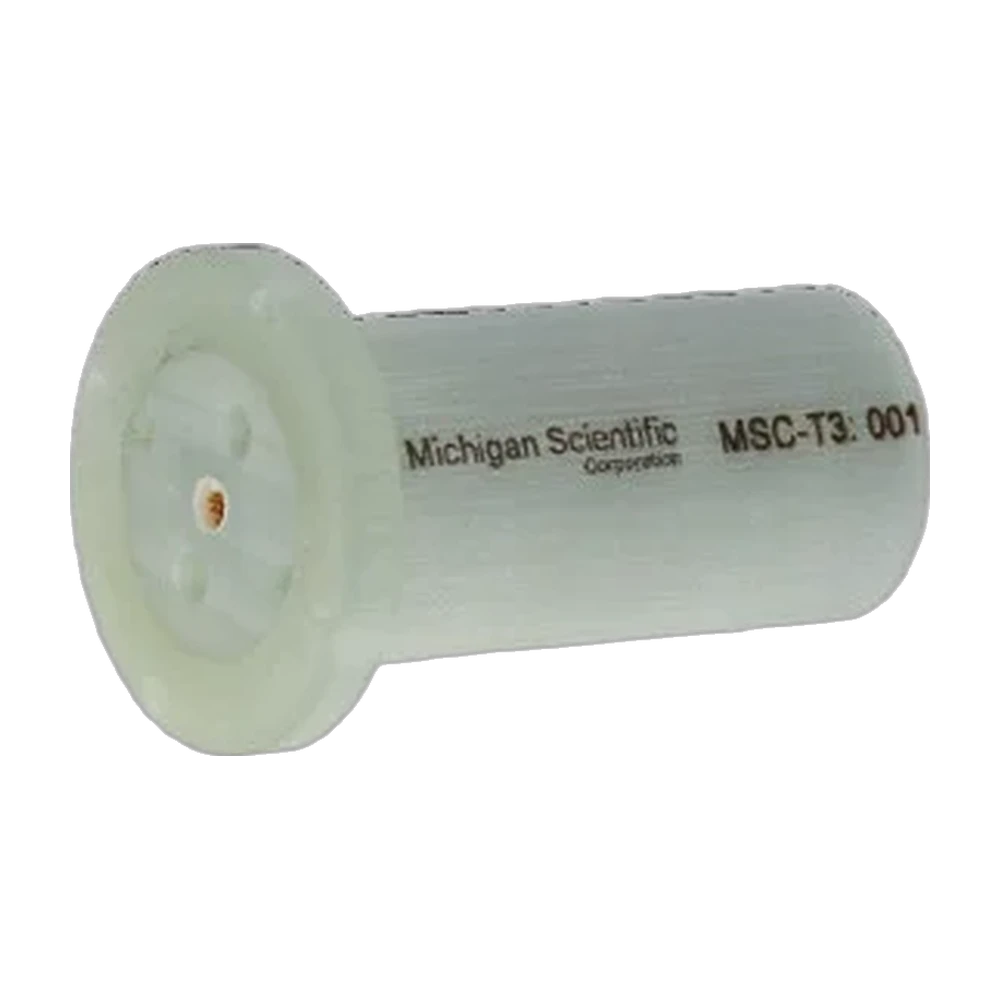
The T3 is an end-of-shaft telemetry transmitter for three channels, configurable for strain gages or thermocouples. It transmits the signals digitally by RF with error checking, at up to 7 kHz per channel. Its compact, bearing-free housing has no wear parts and needs no periodic maintenance; it has been proven at 24 000 rpm, and no upper speed limit has been established. The housing is 63.1 mm long, with a 28.4 mm diameter body and a 41.3 mm flange. Power comes by induction, and the receiver gives a ±10 V analog output per channel.
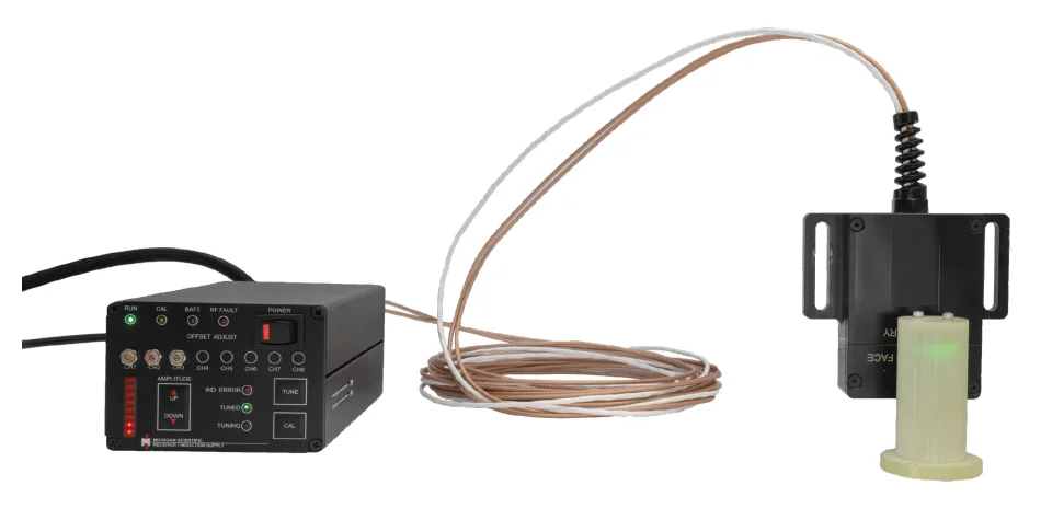
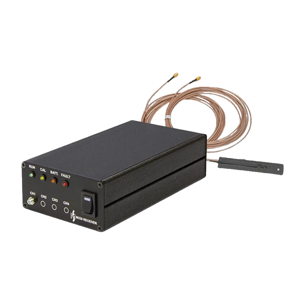
The T3 mounts on the end of the shaft, ideally on a slotted adapter that Michigan Scientific can machine, through four #4-40 clearance holes on a 36.45 mm bolt circle. The primary inductive coil paddle is placed about 3 to 5 mm from the T3, perpendicular to it and clear of metal objects. The receiving antennas, up to 9 m long, sit 1 to 3 m away. The receiver and induction supply share one box, powered at 9 to 36 V DC, with a tuning button; a 3 s shunt calibration sequence runs at power-up.
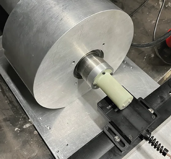
It is designed for long-term tests on high-speed instrumented shafts; its datasheet shows it at the end of a test shaft, facing its induction paddle.
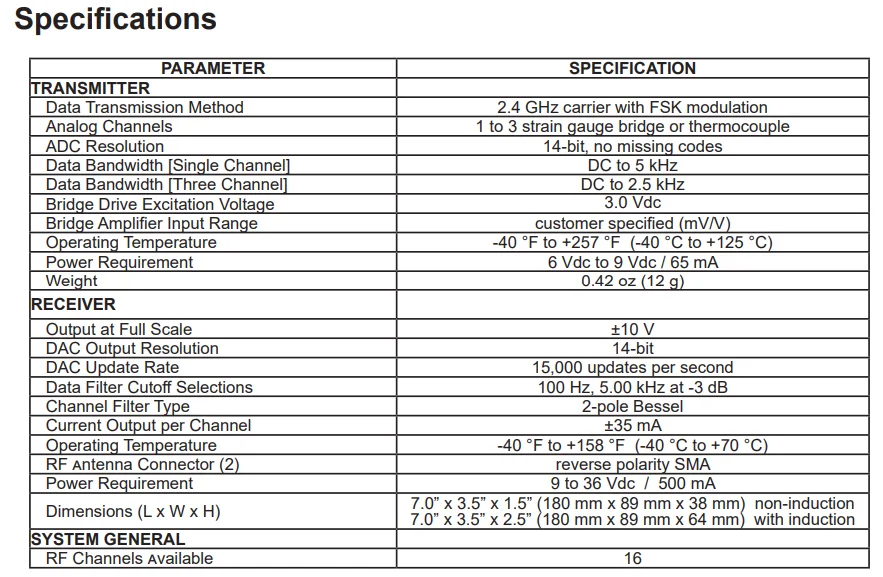
Specifications
| Channels | 3 |
|---|---|
| Input | Strain gage bridge · Thermocouple (configurable) |
| Output | Analog voltage (one per channel) |
| Output range | −10 to 10 V |
| Sample rate | 7 kHz (up to, per channel) |
| Transmission distance | 1 to 3 m (loop antenna up to 9 m long) |
| Power source | Induction |
| Mounting | End of shaft (bearing free, no wear parts, no periodic maintenance) |
| Max speed | 24 000 rpm (proven; no upper limit established) |
| Mounting fasteners | 4 × #4-40 (clearance holes) |
| Bolt circle | 36.45 mm |
| Induction gap | 3 to 5 mm (approx.) |
| Dimensions | Ø 28.4 × 63.1 mm (body; flange Ø 41.3 mm) |
Resources
Datasheets and manuals
Drawings
None for this product.
CAD models
None for this product.
Related applications
-
 Efficiency Vehicle efficiency and power mapping Torque and speed measured at each driveline stage, from engine to wheel, so each power loss has a location.
-
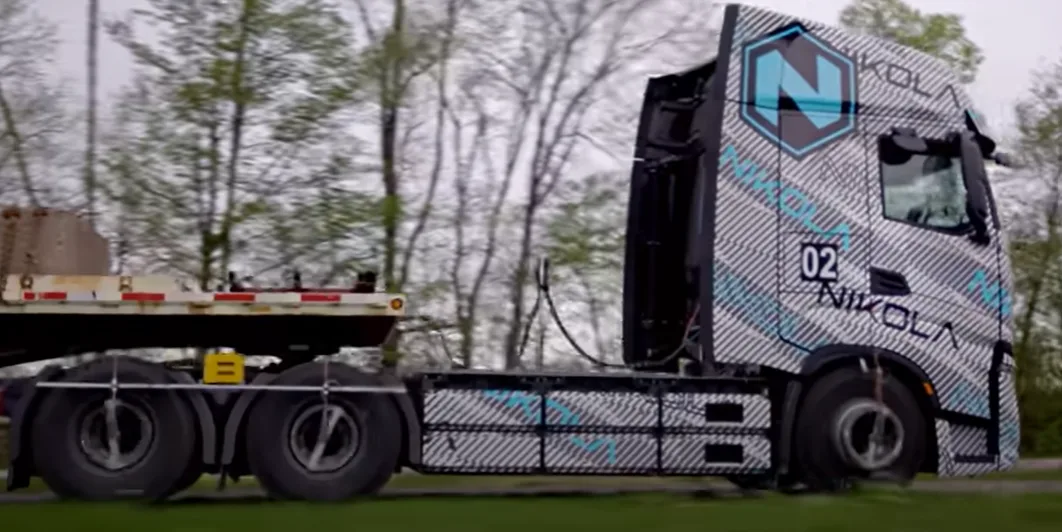 Powertrain Truck solid axle torque Drive torque on a truck solid axle, read by strain gages inside the shaft and brought out at the wheel.
-
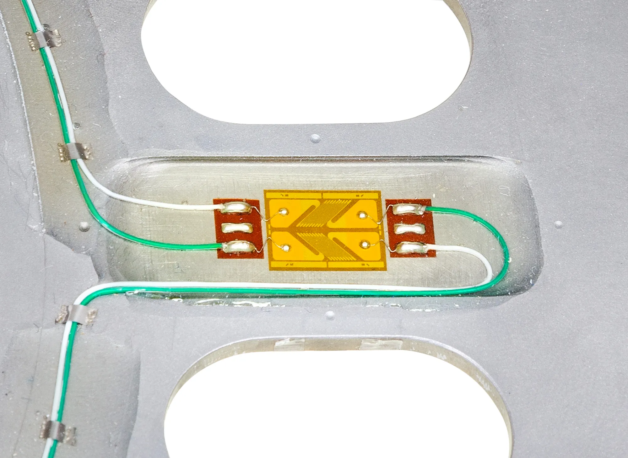 Engine Crankshaft measurements Torque, bending and strain on the production crankshaft with the engine running, in the vehicle or on the dyno.
-
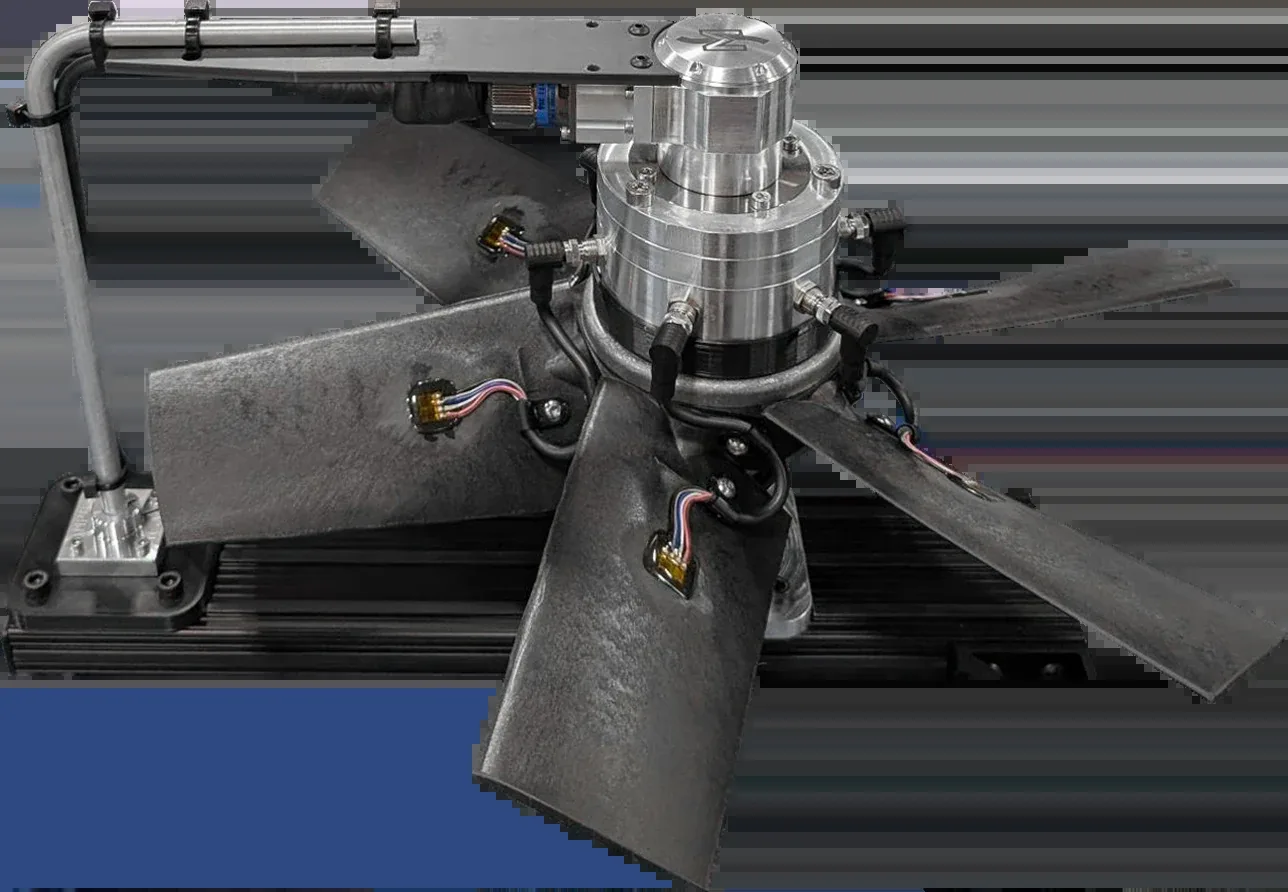 Turbines Fan and turbine blades Strain and temperature from many points on the blades, recorded together while the rotor turns.
In the same family
- Eight channels Model T8
End-of-shaft, induction-powered telemetry for eight strain gage bridge or thermocouple channels, 16-bit, in a bearing-free housing proven at 24 000 rpm.
- One channel only M540
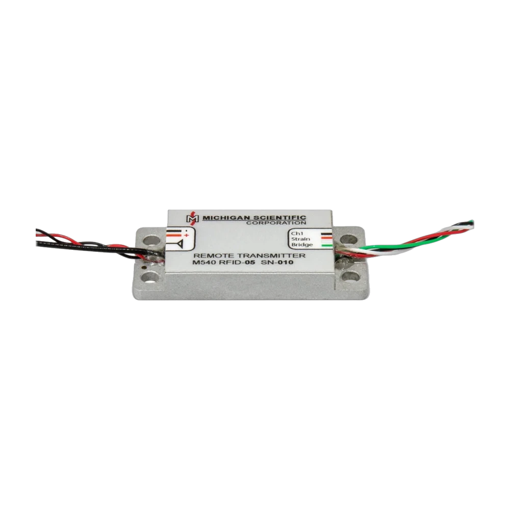
Digital telemetry system for one to three strain gage bridge or thermocouple channels, with a 14-bit transmitter weighing 12 g and a ±10 V analog receiver.
- Not on the shaft end M320
Digital telemetry system for up to three strain gage bridge or thermocouple channels, 12-bit at 3 kHz, with a 38.1 × 40.6 × 8.9 mm transmitter weighing 25 g.
A question on this product?
Describe the measurement. An application engineer answers.
More details to give? Use the full contact form.