
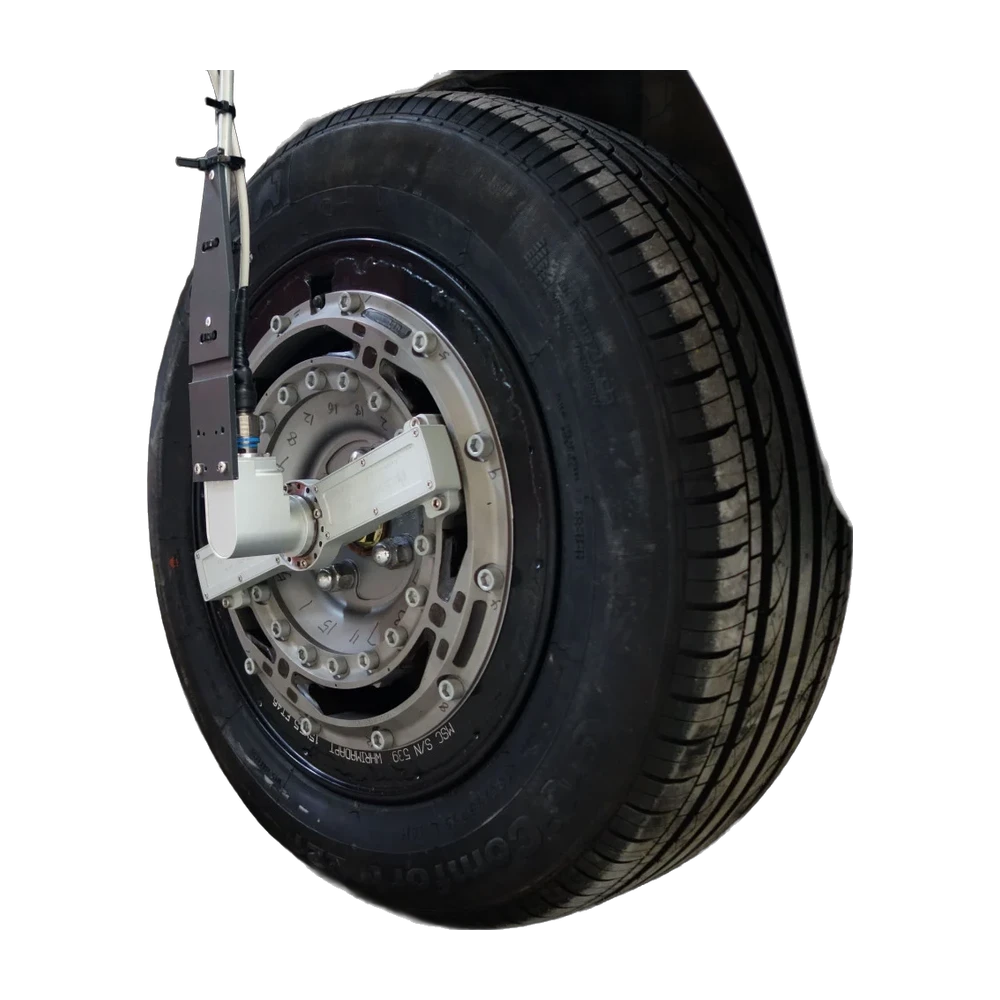
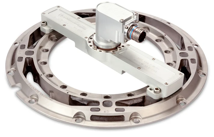
LW12.8-50 wheel force transducer
Six-axis wheel force transducer for motorcycles, 15.5 kN radial and 5.3 kN lateral, with telemetry, induction power and encoder built into the transducer.
Six-axis wheel force transducer for motorcycles, ATVs and small cars, 25 kN radial and 8.9 kN lateral, sealed to IP67, with a swappable slip ring or telemetry package.
Six-axis wheel force transducer for ATVs, utility and other lightweight vehicles, 35.6 kN radial and 17.8 kN lateral, in stainless steel, with amplifier and slip ring.
Six-axis wheel force transducer for passenger cars and light-duty trucks, 50 kN radial, 25 kN lateral and 6.5 kN·m, in stainless steel, with amplifier and slip ring.
Six-axis telemetry wheel force transducer for passenger cars and light-duty trucks, 50 kN radial and 25 kN lateral, with induction-powered electronics built into the transducer.
Six-axis wheel force transducer for passenger cars and light-duty trucks, 50 kN radial and 25 kN lateral, IP67, rated −40 to 177 °C, with slip ring or telemetry.
Six-axis wheel force transducer for passenger cars and light-duty trucks, 60 kN radial, 30 kN lateral and 9.0 kN·m, in stainless steel, with amplifier and slip ring.
Six-axis wheel force transducer for passenger cars, SUVs and light trucks, 60 kN radial and 35 kN lateral, IP67, rated −40 to 177 °C, with slip ring or telemetry.
Six-axis wheel force transducer for passenger cars, SUVs and light-duty trucks, 65 kN radial, 35 kN lateral and 10.5 kN·m, IP67, with slip ring or telemetry.
Six-axis wheel force transducer for pick-up trucks, vans and SUVs, 90 kN radial and 45 kN lateral, for 16 in and larger single or dual wheels, with slip ring transmission.
Six-axis wheel force transducer for forklift trucks and other heavy vehicles with small wheels, 93 kN radial and 45 kN lateral, for 10 in and larger wheels.
Six-axis wheel force transducer for commercial vehicles, medium-duty trucks, skid steers and large forklifts, 133 kN radial and 66 kN lateral, for 15 in and larger single or dual wheels.
Six-axis wheel force transducer for the front axle of class 8 trucks, 150 kN radial and 75 kN lateral, sealed to IP67, with swappable slip ring or telemetry transmission.
Six-axis wheel force transducer for standard hubs with a 425 mm PCD, 700 kN per force and 275 kN·m per moment, sealed to IP67, with slip ring or telemetry.
Six-axis wheel force transducer for commercial vehicles, medium-duty trucks, skid steers and large forklifts, 178 kN radial and 89 kN lateral, for 15 in and larger single or dual wheels.
Six-axis wheel force transducer for class 8 trucks, 222 kN radial and 111 kN lateral, in stainless steel, for 19.5 in and larger single or dual wheels, with slip ring.
Six-axis wheel force transducer for class 8 trucks and large off-road vehicles, 300 kN radial and 150 kN lateral, in stainless steel, for 20 in and larger wheels.
Six-axis wheel force transducer for class 8 trucks and large off-road vehicles, 445 kN radial, 222 kN lateral and 108 kN·m, for 20 in and larger wheels.
Six-axis wheel force transducer for class 8 trucks, large off-road vehicles and heavy equipment, 445 kN radial and 225 kN lateral, in stainless steel, for 22.5 in and larger wheels.
- 15.5 kN
- Fx, Fz capacity
- 5.3 kN
- Fy capacity
- 1.6 / 3.4 kN·m
- Moment capacity
- < 1 % FS
- Non-linearity
- 25 kN
- Fx, Fz capacity
- 8.9 kN
- Fy capacity
- 2.0 / 3.4 kN·m
- Moment capacity
- ≤ 0.25 % FS (forces, My)
- Non-linearity
- 35.6 kN
- Fx, Fz capacity
- 17.8 kN
- Fy capacity
- 5.4 kN·m
- Moment capacity
- ≤ 0.25 % FS
- Non-linearity
- 50 kN
- Fx, Fz capacity
- 25 kN
- Fy capacity
- 6.5 kN·m
- Moment capacity
- ≤ 0.2 % FS (Fx, Fz, My)
- Non-linearity
- 50 kN
- Fx, Fz capacity
- 25 kN
- Fy capacity
- 6.5 kN·m
- Moment capacity
- ≤ 0.2 % FS (Fx, Fz, My)
- Non-linearity
- 50 kN
- Fx, Fz capacity
- 25 kN
- Fy capacity
- 6.5 kN·m
- Moment capacity
- ≤ 0.25 % FS
- Non-linearity
- 60 kN
- Fx, Fz capacity
- 30 kN
- Fy capacity
- 9.0 kN·m
- Moment capacity
- ≤ 0.5 % FS
- Non-linearity
- 60 kN
- Fx, Fz capacity
- 35 kN
- Fy capacity
- 8.0 / 9.0 kN·m
- Moment capacity
- ≤ 0.25 % FS
- Non-linearity
- 65 kN
- Fx, Fz capacity
- 35 kN
- Fy capacity
- 10.5 kN·m
- Moment capacity
- ≤ 0.2 % FS (forces, My)
- Non-linearity
- 90 kN
- Fx, Fz capacity
- 45 kN
- Fy capacity
- 15 / 20 kN·m
- Moment capacity
- ≤ 0.5 % FS
- Non-linearity
- 93 kN
- Fx, Fz capacity
- 45 kN
- Fy capacity
- 9.5 kN·m
- Moment capacity
- < 1 % FS
- Non-linearity
- 133 kN
- Fx, Fz capacity
- 66 kN
- Fy capacity
- 30 kN·m
- Moment capacity
- ≤ 0.5 % FS (Fx, Fz)
- Non-linearity
- 150 kN
- Fx, Fz capacity
- 75 kN
- Fy capacity
- 40 kN·m
- Moment capacity
- ≤ 0.5 % FS
- Non-linearity
- 700 kN
- Fx, Fz capacity
- 700 kN
- Fy capacity
- 275 kN·m
- Moment capacity
- ≤ 0.5 % FS
- Non-linearity
- 178 kN
- Fx, Fz capacity
- 89 kN
- Fy capacity
- 40 kN·m
- Moment capacity
- ≤ 0.5 % FS (Fx, Fz)
- Non-linearity
- 222 kN
- Fx, Fz capacity
- 111 kN
- Fy capacity
- 68 kN·m
- Moment capacity
- ≤ 1 % FS
- Non-linearity
- 300 kN
- Fx, Fz capacity
- 150 kN
- Fy capacity
- 81 kN·m
- Moment capacity
- ≤ 1 % FS
- Non-linearity
- 445 kN
- Fx, Fz capacity
- 222 kN
- Fy capacity
- 108 kN·m
- Moment capacity
- ≤ 1 % FS
- Non-linearity
- 445 kN
- Fx, Fz capacity
- 225 kN
- Fy capacity
- 135 kN·m
- Moment capacity
- ≤ 1 % FS
- Non-linearity
- OutputsFx Fy Fz · Mx My Mz
- Also measuredX and Z acceleration (X, Y, Z on the LW50) · wheel speed and angle
- Signal outputanalog · CAN · Ethernet · CAN FD and EtherCAT on the CT3
Motorcycle wheel force transducer, 15.5 kN
The LW-MC-3.5K measures all the wheel forces and moments on a motorcycle: vertical, lateral and longitudinal forces, and camber, steer and torque moments. Its 4-arm strain gage bridges are rated 15.5 kN (3,500 lb) on Fx and Fz, 5.3 kN (1,200 lb) on Fy, 1.6 kN·m on Mx and Mz and 3.4 kN·m on My. The telemetry and induction power electronics and the magnetic encoder wheel are packaged into the transducer, 2.25 kg with them. It is weatherproof and temperature compensated, operates from −40 to 125 °C, resolves the wheel angle to 0.25° and adapts to 11 in and larger wheels.
The transducer pilots into the modified wheel with sixteen M8 × 1.25 screws, and the hub adapter, made to the offset of the production wheel, pilots into it with eighteen more, all torqued crosswise to 20 N·m (15 lb·ft). An adjustable bracket holds the telemetry stator outboard of the transducer, aligned with a spacer. The CT2-TEL box, powered at 10 to 36 V DC, supplies the induction power, runs a shunt calibration at power-up, zeroes the transducer and gives the loads in motorcycle coordinates.
It is the LW series model for motorcycles. On the same motorcycle, it gives the forces and moments at the wheel while a handlebar torque transducer measures the input of the rider.
Wheel force transducer for motorcycles and small cars, 25 kN
The LW25 measures all the wheel forces and moments on motorcycles, ATVs and small cars, with X and Z accelerations. It is rated 25 kN (5,600 lbf) on Fx and Fz, 8.9 kN (2,000 lbf) on Fy, 2.0 kN·m on Mx and Mz and 3.4 kN·m on My, for a static weight of 550 kg. Non-linearity is 0.25 % of full scale or less on the forces and My, crosstalk after correction 0.4 % or less. The IP67 transducer weighs 1.5 kg, operates from −40 to 125 °C and fits 11 in and larger wheels, or 8 in with a two-piece rim adapter.
The hub and rim adapters each bolt to the transducer with sixteen M8 × 1.25 screws, tightened in a star pattern to 40 N·m; a motorcycle hub adapter suits a double-sided swing arm. The signals leave the wheel through an outboard slip ring, at 0.17° angular resolution, or a factory-mated telemetry and encoder ring, at 0.25°, whose stator is set with an alignment tool on an adjustable bracket. The CT3 box, powered at 9 to 36 V DC, zeroes the transducer, checks the shunt calibration and transforms the coordinates.
Its IP67 design suits the harshest track and off-road measurements; on a motorcycle, the telemetry package mounts outboard. Non-spinning, the transducer monitors and controls laboratory test rigs.
Wheel force transducer for ATVs and small vehicles, 35.6 kN
The LW9.5 measures all the wheel forces and moments on ATVs, utility and other lightweight vehicles: vertical, lateral and longitudinal forces, and camber, steer and torque moments. Its 4-arm strain gage bridges are rated 35.6 kN (8,000 lb) on Fx and Fz, 17.8 kN (4,000 lb) on Fy and 5.4 kN·m on all three moments, with non-linearity of 0.25 % of full scale or less. The stainless steel transducer is weatherproof and temperature compensated, operates from −40 to 125 °C and adapts to 10 in and larger wheels. A matching amplifier adds X and Z accelerations and digitizes the signals before the slip ring; angular resolution is 0.17°.
The hub adapter bolts to the transducer with thirty-two 1/4-20 screws and the rim adapter with twenty-four, torqued crosswise to 13 N·m; four more hold the amplifier, sealed by O-rings and matched to its transducer. The slip ring, with a 512-pulse encoder, stays on the amplifier; a magnetic restraint and rod hold its stator on non-steered wheels, a stator angle corrector on steered ones. The CT2 box, powered at 9 to 36 V DC, zeroes the transducer on a hoist or on the road, runs the shunt calibration and gives the loads in vehicle coordinates.
The Michigan Tech Blizzard Baja team fitted an LW9.5 to its off-road car on custom adapters. On a utility vehicle, it records the force falling to zero in flight and peaking at landing after a ramp.
Wheel force transducer for cars, 50 kN
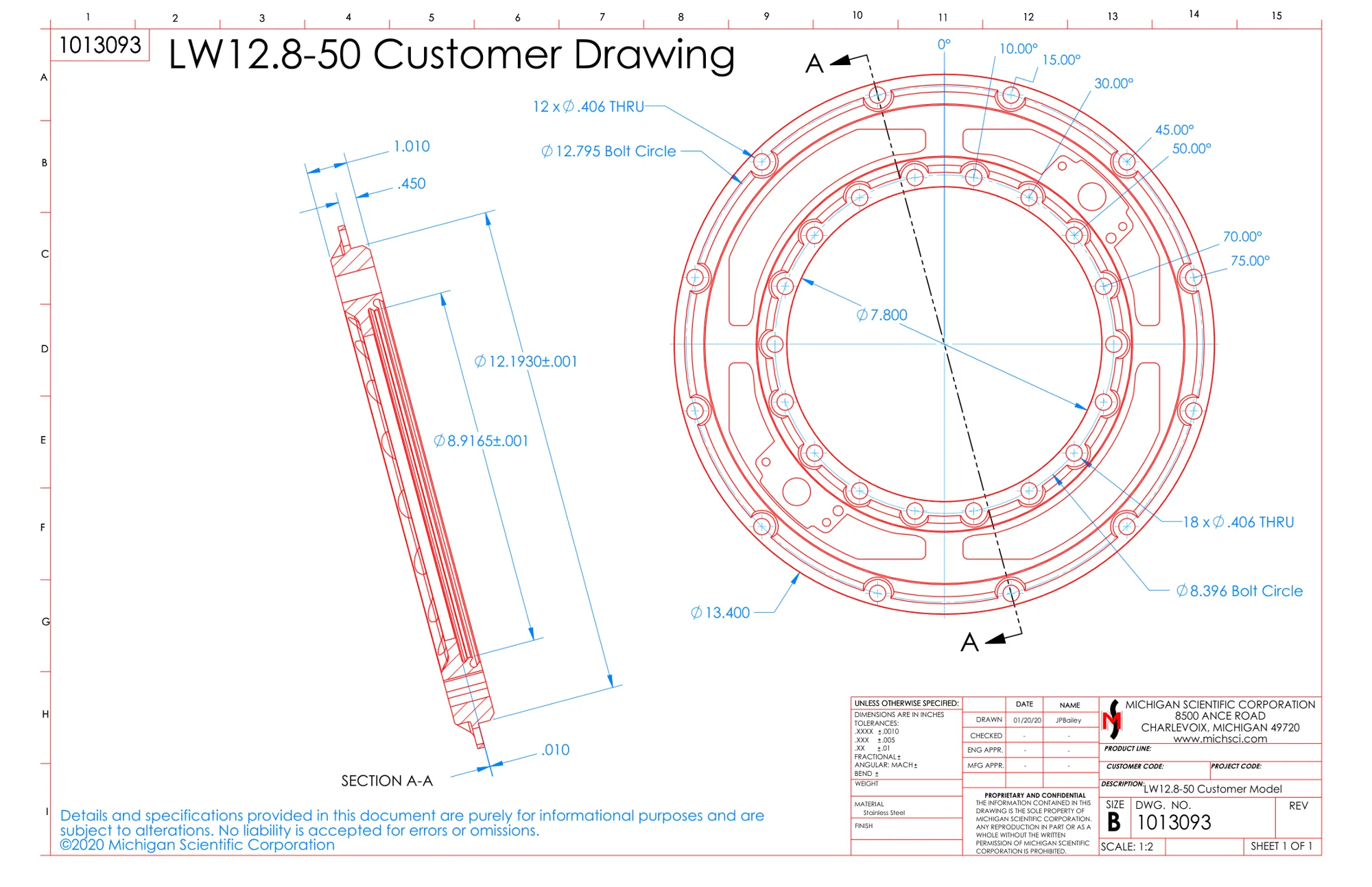
The LW12.8-50 measures all the wheel forces and moments on passenger cars and light-duty trucks, with X and Z accelerations. Its 4-arm strain gage bridges are rated 50 kN (11,200 lb) on Fx and Fz, 25 kN (5,600 lb) on Fy and 6.5 kN·m (4,800 lbf·ft) on all three moments. Non-linearity is 0.2 % of full scale or less on Fx, Fz and My, cross-axis sensitivity after correction below 0.5 %. The stainless steel ring, Ø 340.36 × 25.65 mm, is weatherproof, temperature compensated and tested to SAE J328 fatigue strength; it operates from −40 to 125 °C and adapts to 12 in and larger wheels.
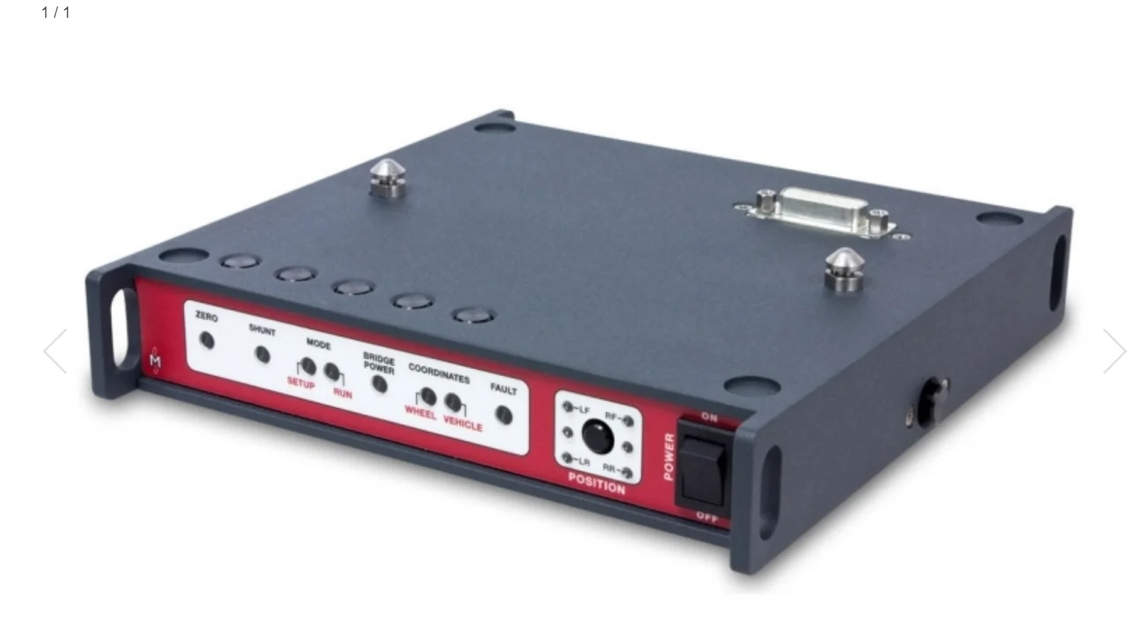
The hub adapter bolts to the inner circle of eighteen holes and the rim adapter to the outer circle of twelve, with M10 × 1.5 screws torqued crosswise to 81 N·m; design guides give their geometry. The amplifier, matched to the transducer and sealed by O-rings, carries a 20-circuit slip ring with a 512-pulse encoder; a magnetic restraint and rod hold its stator on non-steered wheels, a stator angle corrector on steered ones. The CT2 box, powered at 9 to 36 V DC, zeroes the transducer, runs the shunt calibration and resolves the loads into vehicle axes.
It is the LW series model for road load data on passenger cars and SUVs, recorded on proving ground surfaces and over single events such as a pothole. It can also monitor and control laboratory tests.
Telemetry wheel force transducer for cars, 50 kN
The LW12.8-50-TEL measures all the wheel forces and moments on passenger cars and light-duty trucks. Its 4-arm strain gage bridges are rated 50 kN (11,200 lb) on Fx and Fz, 25 kN (5,600 lb) on Fy and 6.5 kN·m on all three moments, with non-linearity of 0.2 % of full scale or less on Fx, Fz and My. The telemetry and induction power electronics are packaged into the weatherproof transducer, 6.0 kg with them. Data is sent at 2,200 Hz with 16-bit resolution, the wheel angle resolved to 0.25°. It operates from −40 to 125 °C and adapts to 14 in and larger wheels.
The stainless steel or titanium hub adapter and the rim adapter bolt to the transducer with M10 screws torqued to 81 N·m; narrow-head screws from Michigan Scientific fit the rim side. The telemetry stator, which holds the receiver, induction coil and encoder pick-ups, mounts inboard on an adjustable bracket, set with an alignment tool. The CT2-TEL box, powered at 10 to 36 V DC, supplies the induction power, zeroes the transducer and transforms the loads; the wheel comes off without removing the electronics.
With no cable through the hub, it is used to test vehicles on snow and ice, where the transducer stays at the wheel in the cold and the wet.
Wheel force transducer for cars, 50 kN, up to 177 °C
The LW50 measures all the wheel forces and moments on passenger cars and light-duty trucks. It is rated 50 kN (11,200 lbf) on Fx and Fz, 25 kN (5,620 lbf) on Fy and 6.5 kN·m on all three moments, for a static weight of 1,020 kg. Non-linearity and hysteresis are 0.25 % of full scale or less, cross-axis sensitivity after correction 0.4 % or less. The IP67 transducer, Ø 342.90 × 21.59 mm, weighs 4.4 kg, operates from −40 to 177 °C and adapts to 12 in and larger wheels.
Its inner circle has sixteen M10 × 1.5 threaded holes, its outer circle sixteen through holes. With the outboard slip ring, the amplifier package mounts onto the transducer, adds X, Y and Z accelerations up to ±100 g and digitizes the signals; a high-resolution optical encoder gives position and speed, at 0.17°. The inboard telemetry package uses a magnetic encoder and an induction-powered stator. The CT3 box resolves the loads in real time, with zero, shunt calibration and zero angle functions, a front display and a web page over USB.
It is designed for the harshest track and off-road measurements on passenger cars and light-duty trucks, and for non-spinning applications that monitor and control laboratory test rigs.
Wheel force transducer for cars, 60 kN
The LW12.8-60 measures all the wheel forces and moments on passenger cars and light-duty trucks, with X and Z accelerations. Its 4-arm strain gage bridges are rated 60 kN (13,500 lb) on Fx and Fz, 30 kN (6,750 lb) on Fy and 9.0 kN·m (6,600 lbf·ft) on all three moments. Non-linearity is 0.5 % of full scale or less, hysteresis and cross-axis sensitivity after correction below 0.5 %. The rugged stainless steel ring, Ø 340.36 × 25.65 mm, is weatherproof and temperature compensated; it operates from −40 to 125 °C and adapts to 13 in and larger wheels.
It has the outside dimensions of the LW12.8-50, with twenty-four holes on its inner bolt circle and twenty on the outer. Design guides set the critical adapter features: Michigan Scientific machines hub adapters from 17-4 H1100 stainless steel and rim adapters from 6061-T6 aluminum forgings, and checks each assembly by FEA to SAE J328. The matching amplifier mounts onto the transducer, digitizes the signals before the slip ring and performs remote shunt calibration; the CT2 box handles coordinate transformation and crosstalk compensation.
Being completely weatherproof, it is made for on-road and off-road measurements in all conditions, and it can also be used to monitor and control laboratory tests.
Wheel force transducer for cars and SUVs, 60 kN
The LW60 measures all the wheel forces and moments on passenger cars, SUVs and light trucks, with X and Z accelerations up to ±100 g. It is rated 60 kN (13,400 lb) on Fx and Fz, 35 kN (7,850 lb) on Fy, 8.0 kN·m on Mx and Mz and 9.0 kN·m on My, for a static weight of 1,225 kg. Non-linearity and hysteresis are 0.25 % of full scale or less, cross-axis sensitivity after correction 0.4 % or less. The IP67 transducer, Ø 342.90 × 26.67 mm, weighs 5.7 kg, operates from −40 to 177 °C and adapts to 12 in and larger wheels.
Sixteen M10 × 1.5 screws pass through the transducer into the rim adapter and twenty-four fasten the hub adapter, torqued crosswise to 81 N·m. The amplifier, matched to the transducer, aligns on a flat and carries a 20-circuit slip ring with a 512-pulse encoder; a magnetic restraint and rod hold its stator on non-steered wheels, a stator angle corrector on steered ones. With the CT3 interface box, powered at 9 to 36 V DC, the system is zeroed, its shunt calibration checked and the loads resolved into vehicle axes.
Its IP67 design suits track and off-road measurements and non-spinning test rigs. The telemetry package mounts inboard on cars and SUVs, or outboard for machinery applications.
Wheel force transducer for cars and SUVs, 65 kN
The LW65 measures all the wheel forces and moments on passenger cars, SUVs and light-duty trucks, with X and Z accelerations up to ±100 g. It is rated 65 kN (14,500 lb) on Fx and Fz, 35 kN (7,850 lb) on Fy and 10.5 kN·m (7,700 lbf·ft) on all three moments, for a static weight of 1,320 kg. Non-linearity is 0.2 % of full scale or less on the forces and My, cross-axis sensitivity after correction 0.4 % or less. The IP67 transducer operates from −40 to 177 °C and adapts to 12 in and larger wheels; angular resolution is 0.17°.
Twenty-four M10 × 1.5 screws pass through the transducer into the rim adapter and twenty-four more fasten the hub adapter, torqued crosswise to 81 N·m; design guides give both adapters. With the slip ring, the amplifier carries a 20-circuit slip ring with a 512-pulse encoder, its stator held by a restraint rod or a stator angle corrector. With telemetry, a factory-mated telemetry and encoder ring feeds an inboard stator set with an alignment tool, and the CT2-TEL box supplies the induction power.
Its IP67 design suits the harshest track and off-road measurements, and non-spinning applications that monitor and control laboratory test rigs. A Michigan Scientific video shows its telemetry set fitted to the front hub of a car.
Wheel force transducer for pick-ups and vans, 90 kN
The LW-2T-20K measures all the wheel forces and moments on light and heavy-duty pick-up trucks, vans and SUVs. Four-arm strain gage bridges give independent signals for the vertical, lateral and longitudinal forces, up to 90 kN radial (Fx, Fz) and 45 kN lateral (Fy), and for the camber, steer and torque moments, 15 kN·m (Mx, Mz) and 20 kN·m (My). Non-linearity is 0.5 % of full scale or less, crosstalk after correction below 1 %. The weatherproof, temperature-compensated ring, Ø 374.65 × 38.10 mm, operates from −40 to 125 °C. Its amplifier package adds X and Z accelerations and an encoder resolving 0.17°.
Rim and hub adapters follow the model's design guides and keep the production wheel offset. Sixteen M14 bolts join the rim adapter and twenty-four the hub adapter, tightened crosswise to 136 N·m; the wheel is balanced once assembled. The matched amplifier and slip ring mount after the lug nuts. A restraint rod to a magnetic bracket holds the slip ring stator, or the stator angle correction device on steered wheels. The CT2 or CT3 interface box, powered at 9 to 36 V DC, runs the shunt calibration and the zero, wheel lifted and turned two revolutions.
It is used for on-road and off-road measurements in all conditions, one transducer measuring the combined loads of a dual wheel set or a single tire, and also to monitor and control laboratory tests.
Forklift wheel force transducer, 93 kN
The LW9.5-HS measures all the wheel forces and moments on forklift trucks and other heavy vehicles with small wheels: vertical, lateral and longitudinal forces, and camber, steer and torque moments. Its 4-arm strain gage bridges are rated 93 kN (21,000 lb) on Fx and Fz, 45 kN (10,000 lb) on Fy and 9.5 kN·m (7,000 lbf·ft) on all three moments. Non-linearity is below 1 % of full scale, hysteresis and cross-axis sensitivity after correction below 0.5 %. The rugged stainless steel transducer is weatherproof and temperature compensated, operates from −40 to 125 °C and adapts to 10 in and larger wheels.
The matching amplifier package mounts onto the transducer. It amplifies and digitizes the strain gage, encoder and accelerometer signals before the slip ring, adds X and Z accelerations up to 55 g and performs remote shunt calibration; its internal smart chip holds the calibration, zero and shunt values. A high-resolution encoder gives position and speed, at 0.17°. The CT2 box performs coordinate transformation and crosstalk compensation in real time, with zero, shunt calibration and bridge power off functions, set up from an embedded web page.
Being completely weatherproof, it is designed for testing forklift trucks in all conditions, and it can also be used to monitor and control laboratory tests.
Medium-duty wheel force transducer, 133 kN
The LW-2T-30K measures all the wheel forces and moments on commercial vehicles, skid steers, medium-duty trucks, off-road equipment and large forklift trucks. Four-arm strain gage bridges give independent signals for the three forces, up to 133 kN radial (Fx, Fz) and 66 kN lateral (Fy), and for the camber, steer and torque moments, 30 kN·m each. Non-linearity is 0.5 % of full scale or less on Fx, Fz and My, 0.75 % on the others; crosstalk after correction stays below 0.5 %. The weatherproof, temperature-compensated transducer, Ø 360.68 mm, fits hub bolt patterns of 265 mm and smaller and operates from −40 to 125 °C, with X and Z accelerations and 0.17° angular resolution.
Rim and hub adapters follow the LW-2T-30K/40K design guides; the LW-2T-30K manual covers single, front and dual wheels. Twenty-four M14 bolts join the transducer to each adapter, tightened to 150 N·m. After the wheel nuts, the matched amplifier and its ten-circuit slip ring bolt onto the transducer, sealed by O-rings. A restraint rod to a magnetic bracket holds the slip ring stator, or the stator angle correction device on steered wheels. The CT3 interface box, powered at 9 to 36 V DC, runs the shunt calibration and the zero, wheel lifted and turned two revolutions.
It is used for on-road and off-road measurements, one transducer measuring the combined loads of a dual wheel set or a single tire, and also to monitor and control laboratory tests.
Thin wheel force transducer for truck front axles, 150 kN
The LW150 measures all the wheel forces and moments on the front axle of class 8 trucks: vertical, lateral and longitudinal forces up to 150 kN radial (Fx, Fz) and 75 kN lateral (Fy), and camber, steer and torque moments of 40 kN·m each. The maximum recommended static load is 4,400 kg. Non-linearity and hysteresis are 0.5 % of full scale or less, crosstalk after correction 1 %. Of thin design and sealed to IP67, the transducer weighs 20.9 kg and operates from −40 to 177 °C. Its ± 100 g accelerometers give X and Z accelerations; angular resolution is 0.17°.
With an outboard slip ring, it fits 19.5 in and larger wheels: the amplifier package mounts onto the transducer and digitizes the signals before the slip ring. Inboard telemetry, for 22.5 in and larger wheels, keeps the assembly within the vehicle width; its stator, mounted close to the rotating telemetry ring, holds the receiver, the encoder pick-ups and the induction coil, and an induction module carries the smart chip. The CT3 interface box performs the zero, shunt calibration and zero angle functions and is set up from its embedded web page, over USB.
Staying within the vehicle width, it suits on-road testing of class 8 trucks; its IP67 design also covers the harshest track and off-road measurements.
Wheel force transducer, 700 kN
The LW700 measures all the wheel forces and moments: vertical, lateral and longitudinal forces up to 700 kN each (Fx, Fy, Fz), and camber, steer and torque moments of 275 kN·m each. The maximum recommended static load is 23,800 kg. Non-linearity and hysteresis are 0.5 % of full scale or less, and cross-axis sensitivity after correction 0.2 %. Of robust IP67 design, the transducer weighs 64.5 kg and fits standard hubs with a 425 mm pitch circle diameter. Its ± 100 g accelerometers give X and Z accelerations, and an encoder gives wheel position and speed.
In spinning use, the signals leave through an outboard slip ring, with the amplifier package mounted onto the transducer, or through inboard telemetry, whose stator, mounted close to the rotating telemetry ring, holds the receiver, the encoder pick-ups and the induction coil; the CT3 box then also supplies the induction power. The CT3 performs coordinate transformation and crosstalk, offset and polarity correction, with zero, shunt calibration check and zero angle functions; its embedded web page, reached over USB, sets up the system and moves the measurement origin.
Its robust IP67 design suits the harshest track and off-road measurements; in non-spinning applications, the LW700 is used to monitor and control laboratory test rigs.
Medium-duty wheel force transducer, 178 kN
The LW-2T-40K measures all the wheel forces and moments on commercial vehicles, skid steers, medium-duty trucks, off-road equipment and large forklift trucks. Four-arm strain gage bridges give independent signals for the three forces, up to 178 kN radial (Fx, Fz) and 89 kN lateral (Fy), and for the camber, steer and torque moments, 40 kN·m each. Non-linearity is 0.5 % of full scale or less on Fx, Fz and My, 0.75 % on Mx and Mz and 1.5 % on Fy; crosstalk after correction stays below 0.5 %. The weatherproof, temperature-compensated transducer fits hub bolt patterns of 265 mm and smaller and operates from −40 to 125 °C, with X and Z accelerations and 0.17° angular resolution.
Rim and hub adapters follow the LW-2T-30K/40K design guides; the LW-2T-40K manual covers single, front and dual wheels. Twenty-four M14 bolts join the transducer to each adapter, tightened to 150 N·m. After the wheel nuts, the matched amplifier and its ten-circuit slip ring bolt onto the transducer, sealed by O-rings. A restraint rod to a magnetic bracket holds the slip ring stator, or the stator angle correction device on steered wheels. The CT3 interface box, powered at 9 to 36 V DC, runs the shunt calibration and the zero, wheel lifted and turned two revolutions.
It is used for on-road and off-road measurements, one transducer measuring the combined loads of a dual wheel set or a single tire, and also to monitor and control laboratory tests.
Heavy-duty wheel force transducer, 222 kN
The LW-2T-50K measures all the wheel forces and moments on class 8 trucks. Four-arm strain gage bridges give independent signals for the vertical, lateral and longitudinal forces, up to 222 kN radial (Fx, Fz) and 111 kN lateral (Fy) at the tire patch, and for the camber, steer and torque moments, 68 kN·m each. Non-linearity, hysteresis and crosstalk after correction are within 1 % of full scale. The stainless steel transducer is environmentally protected and temperature compensated, and operates from −40 to 125 °C. Its matching amplifier package adds X and Z accelerations, an encoder resolving 0.17° and remote shunt calibration.
The manual covers single and dual-wheel assemblies. Twenty-four ¾-10 bolts join the transducer to each adapter, tightened to 339 N·m; on dual wheels, the inner and outer rim adapters share the same bolts and stand-offs carry the amplifier bar. The matched amplifier and slip ring mount after the wheel nuts. A restraint rod to a magnetic bracket holds the slip ring stator, or the stator angle correction device on steered wheels. The CT2 or CT3 interface box, powered at 9 to 36 V DC, runs the shunt calibration and the zero.
It is used for on-road and off-road measurements, one transducer measuring the combined loads of a dual wheel set or a single tire, and also to monitor and control laboratory tests. On large farm equipment, it serves durability, vehicle dynamics and handling tests.
Heavy-duty wheel force transducer, 300 kN
The LW-2T-60K-S measures all the wheel forces and moments on class 8 trucks and large off-road vehicles. Four-arm strain gage bridges give independent signals for the vertical, lateral and longitudinal forces, up to 300 kN radial (Fx, Fz) and 150 kN lateral (Fy) at the tire patch, and for the camber, steer and torque moments, 81 kN·m each. Non-linearity and crosstalk after correction stay within 1 % of full scale, hysteresis below 0.5 %. The weatherproof stainless steel ring, Ø 469.9 × 119.1 mm, fits 285 mm and 335 mm hub bolt patterns and operates from −40 to 125 °C, with X and Z accelerations and 0.17° angular resolution.
Twenty-four Ø 17.5 mm through holes and M20 × 2.5 threads lie on a Ø 435.6 mm bolt circle. On dual wheels, both rim adapters bolt onto the transducer with the same M20 bolts, then the hub adapter with twenty-four more, tightened with a torque multiplier; stand-offs carry the amplifier bar. A magnetic restraint holds the slip ring stator vertical, or the stator angle correction device on steered wheels. The interface box, a CT2 in the manual and a CT3 in the 2024 datasheet, is powered at 9 to 36 V DC and runs the shunt calibration and the zero.
It is used for on-road and off-road measurements, one transducer measuring the combined loads of a dual wheel set or a single tire, and also to monitor and control laboratory tests.
Heavy-duty wheel force transducer, 445 kN
The LW-2T-100K-S measures all the wheel forces and moments on class 8 trucks and large off-road vehicles. Four-arm strain gage bridges give independent signals for the vertical, lateral and longitudinal forces, up to 445 kN radial (Fx, Fz) and 222 kN lateral (Fy) at the tire patch, and for the camber, steer and torque moments, 108 kN·m each. Non-linearity and crosstalk after correction stay within 1 % of full scale, hysteresis below 0.5 %. The weatherproof stainless steel ring, Ø 469.9 × 119.1 mm, fits 285 mm and 335 mm hub bolt patterns and operates from −40 to 125 °C, with X and Z accelerations and 0.17° angular resolution.
It shares the outline of the LW-2T-60K-S: twenty-four Ø 17.5 mm through holes and M20 × 2.5 threads on a Ø 435.6 mm bolt circle. The rim adapters, single or dual, and the hub adapter each take twenty-four M20 bolts, tightened to 450 N·m. The amplifier and its twenty-circuit slip ring bolt onto the transducer; a magnetic restraint holds the stator vertical. The interface box, a CT2 in the 2017 manual and a CT3 in the 2024 datasheet, is powered from the vehicle and runs the shunt calibration and the zero.
It is used for on-road and off-road measurements, one transducer measuring the combined loads of a dual wheel set or a single tire, and also to monitor and control laboratory tests. It records road load data on class 8 trucks and tractors.
Heavy-equipment wheel force transducer, 445 kN
The LW-2T-100K measures all the wheel forces and moments on class 8 trucks, large off-road vehicles and heavy equipment. Four-arm strain gage bridges give independent signals for the vertical, lateral and longitudinal forces, up to 445 kN radial (Fx, Fz) and 225 kN lateral (Fy) at the tire patch, and for the camber, steer and torque moments, 135 kN·m each. Non-linearity and crosstalk after correction stay within 1 % of full scale, hysteresis below 0.5 %. The environmentally protected, temperature-compensated stainless steel transducer adapts to 22.5 in and larger wheels and operates from −40 to 125 °C.
One transducer takes the combined loads of a dual wheel set or a single tire. The matching amplifier package mounts onto it, amplifies and digitizes the bridge signals before the slip ring, adds X and Z accelerations and an encoder resolving 0.17°, and performs remote shunt calibration. The CT2 interface box makes the coordinate transformation and crosstalk compensation in real time, with zero, shunt calibration and bridge power off functions and analog, CAN and Ethernet outputs; its embedded web page sets up the system and moves the measurement origin.
It is used for on-road and off-road measurements and to monitor and control laboratory tests. On large farm equipment, it serves durability, vehicle dynamics and handling tests.
Specifications
| Measured quantities | Fx · Fy · Fz · Mx · My · Mz |
|---|---|
| Force capacity | Fx 15.5 · Fy 5.3 · Fz 15.5 kN |
| Moment capacity | Mx 1 600 · My 3 400 · Mz 1 600 N·m |
| Non-linearity | ≤ 1 % FS |
| Hysteresis | ≤ 0.5 % FS |
| Crosstalk | ≤ 1 % FS (after compensation) |
| Angle resolution | 0.25° |
| Axes | 6 |
| Sensing principle | Strain gage (4-arm bridges) |
| Output | Analog voltage · CAN · Ethernet |
| Bandwidth | 0.2 kHz (< −0.1 dB; 500 Hz at < −1.0 dB) |
| Sample rate | 2.2 kHz |
| Resolution | 16 bit |
| Signal transmission | Telemetry |
| Supply voltage | 10 to 36 V (about 2.0 A at 13.5 V DC) |
| Power source | Induction |
| Shaft diameter | 146.05 mm (center bore) |
| Bolt circle | 160.02 mm |
| Rim bolt circle | 259.72 mm |
| Dimensions | Ø 273.69 × 33.02 mm |
| Weight | 2.25 kg (with telemetry electronics) |
| Operating temperature | −40 to 125 °C |
| Operating temperature, stationary electronics | −20 to 60 °C (CT2-TEL) |
| Interface box | CT2-TEL |
| Vehicles | Motorcycles |
| Rim size | 11 in (and larger) |
| Measured quantities | Fx · Fy · Fz · Mx · My · Mz |
|---|---|
| Force capacity | Fx 25 · Fy 8.9 · Fz 25 kN |
| Moment capacity | Mx 2 000 · My 3 400 · Mz 2 000 N·m |
| Max static load | 550 kg |
| Non-linearity | Fx ≤ 0.25 · Fy ≤ 0.25 · Fz ≤ 0.25 · Mx ≤ 0.5 · My ≤ 0.25 · Mz ≤ 0.5 % FS |
| Hysteresis | ≤ 0.25 % FS |
| Crosstalk | ≤ 0.4 % FS (after correction) |
| Angle resolution | 0.17° (slip ring; 0.25° with telemetry) |
| Axes | 6 |
| Accelerometer range | 100 g (X and Z) |
| Output | CAN FD · CAN · Ethernet · EtherCAT · Analog voltage (CAN 2.0; EtherCAT and analog with optional modules) |
| Signal transmission | Slip ring · Telemetry (slip ring outboard; telemetry inboard or outboard (motorcycles)) |
| Shaft diameter | 167.64 mm (center bore) |
| Mounting fasteners | 16 × M8 × 1.25 |
| Rim fasteners | 16 × M8 × 1.25 |
| Bolt circle | 190.5 mm |
| Rim bolt circle | 259.72 mm |
| Dimensions | Ø 273.69 × 22.86 mm |
| Weight | 1.5 kg |
| Operating temperature | −40 to 125 °C |
| Protection | IP67 |
| Interface box | CT3 |
| Vehicles | Motorcycles · ATVs · Small cars |
| Rim size | 11 in (and larger; 8 in and larger with a two-piece rim adapter) |
| Measured quantities | Fx · Fy · Fz · Mx · My · Mz |
|---|---|
| Force capacity | Fx 35.6 · Fy 17.8 · Fz 35.6 kN |
| Moment capacity | Mx 5 400 · My 5 400 · Mz 5 400 N·m |
| Non-linearity | ≤ 0.25 % FS |
| Hysteresis | ≤ 0.5 % FS |
| Crosstalk | ≤ 1 % FS (after correction) |
| Angle resolution | 0.17° |
| Axes | 6 |
| Sensing principle | Strain gage (4-arm bridges) |
| Accelerometer range | 55 g (X and Z) |
| Output | Analog voltage · CAN · Ethernet |
| Signal transmission | Slip ring |
| Material | Stainless steel |
| Operating temperature | −40 to 125 °C |
| Interface box | CT2 |
| Vehicles | ATVs · Utility vehicles · Lightweight vehicles |
| Rim size | 10 in (and larger) |
| Measured quantities | Fx · Fy · Fz · Mx · My · Mz |
|---|---|
| Force capacity | Fx 50 · Fy 25 · Fz 50 kN |
| Moment capacity | Mx 6 500 · My 6 500 · Mz 6 500 N·m |
| Non-linearity | Fx ≤ 0.2 · Fy ≤ 0.5 · Fz ≤ 0.2 · Mx ≤ 1 · My ≤ 0.2 · Mz ≤ 1 % FS |
| Hysteresis | ≤ 1 % FS |
| Crosstalk | ≤ 0.5 % FS (after correction) |
| Angle resolution | 0.17° |
| Axes | 6 |
| Sensing principle | Strain gage (4-arm bridges) |
| Accelerometer range | 55 g (X and Z) |
| Output | Analog voltage · CAN · Ethernet |
| Signal transmission | Slip ring |
| Shaft diameter | 198.12 mm (center bore) |
| Mounting fasteners | 18 × Ø 10.31 mm |
| Rim fasteners | 12 × Ø 10.31 mm |
| Bolt circle | 213.26 mm |
| Rim bolt circle | 324.99 mm |
| Fatigue tested to | SAE J328 |
| Dimensions | Ø 340.36 × 25.65 mm |
| Material | Stainless steel |
| Operating temperature | −40 to 125 °C |
| Interface box | CT2 |
| Vehicles | Passenger cars · Light trucks |
| Rim size | 12 in (and larger) |
| Measured quantities | Fx · Fy · Fz · Mx · My · Mz |
|---|---|
| Force capacity | Fx 50 · Fy 25 · Fz 50 kN |
| Moment capacity | Mx 6 500 · My 6 500 · Mz 6 500 N·m |
| Non-linearity | Fx ≤ 0.2 · Fy ≤ 0.5 · Fz ≤ 0.2 · Mx ≤ 1 · My ≤ 0.2 · Mz ≤ 1 % FS |
| Hysteresis | ≤ 1 % FS |
| Crosstalk | ≤ 1 % FS (before compensation) |
| Angle resolution | 0.25° |
| Axes | 6 |
| Sensing principle | Strain gage (4-arm bridges) |
| Sensitivity variation over a revolution | ≤ 1 % FS |
| Rated output | 0.8 mV/V |
| Output | Analog voltage · CAN · Ethernet |
| Bandwidth | 0.2 kHz (< −0.1 dB; 500 Hz at < −1.0 dB) |
| Sample rate | 2.2 kHz |
| Resolution | 16 bit (1.8 N · 0.27 N·m) |
| Signal transmission | Telemetry |
| Supply voltage | 10 to 36 V (about 2.0 A at 13.5 V DC) |
| Power source | Induction |
| Shaft diameter | 198.02 mm (center bore) |
| Mounting fasteners | 18 × Ø 9.91 mm |
| Rim fasteners | 12 × Ø 9.91 mm |
| Bolt circle | 213.26 mm |
| Rim bolt circle | 324.97 mm |
| Fatigue tested to | SAE J328 |
| Dimensions | Ø 340.18 × 25.64 mm |
| Weight | 6 kg (with telemetry electronics) |
| Operating temperature | −40 to 125 °C |
| Operating temperature, stationary electronics | −20 to 60 °C (CT2-TEL) |
| Interface box | CT2-TEL |
| Vehicles | Passenger cars · Light trucks |
| Rim size | 14 in (and larger) |
| Measured quantities | Fx · Fy · Fz · Mx · My · Mz |
|---|---|
| Force capacity | Fx 50 · Fy 25 · Fz 50 kN |
| Moment capacity | Mx 6 500 · My 6 500 · Mz 6 500 N·m |
| Max static load | 1 020 kg |
| Non-linearity | ≤ 0.25 % FS |
| Hysteresis | ≤ 0.25 % FS |
| Crosstalk | ≤ 0.4 % FS (after correction) |
| Angle resolution | 0.17° |
| Axes | 6 |
| Accelerometer range | 100 g (X, Y and Z) |
| Output | CAN FD · CAN · Ethernet · EtherCAT · Analog voltage (CAN 2.0; EtherCAT and analog with optional modules) |
| Signal transmission | Slip ring · Telemetry (slip ring outboard; telemetry inboard) |
| Shaft diameter | 228.6 mm (center bore) |
| Mounting fasteners | 16 × M10 × 1.5 |
| Rim fasteners | 16 × Ø 10.32 mm (through) |
| Bolt circle | 255.27 mm |
| Rim bolt circle | 325.12 mm |
| Dimensions | Ø 342.9 × 21.59 mm |
| Weight | 4.4 kg |
| Operating temperature | −40 to 177 °C |
| Protection | IP67 |
| Interface box | CT3 |
| Vehicles | Passenger cars · Light trucks |
| Rim size | 12 in (and larger) |
| Measured quantities | Fx · Fy · Fz · Mx · My · Mz |
|---|---|
| Force capacity | Fx 60 · Fy 30 · Fz 60 kN |
| Moment capacity | Mx 9 000 · My 9 000 · Mz 9 000 N·m |
| Non-linearity | ≤ 0.5 % FS |
| Hysteresis | ≤ 0.5 % FS |
| Crosstalk | ≤ 0.5 % FS (after correction) |
| Angle resolution | 0.17° |
| Axes | 6 |
| Sensing principle | Strain gage (4-arm bridges) |
| Accelerometer range | 55 g (X and Z) |
| Output | Analog voltage · CAN · Ethernet |
| Signal transmission | Slip ring |
| Shaft diameter | 198.12 mm (center bore) |
| Mounting fasteners | 24 × Ø 10.31 mm |
| Rim fasteners | 20 × Ø 10.31 mm |
| Bolt circle | 213.26 mm |
| Rim bolt circle | 324.99 mm |
| Dimensions | Ø 340.36 × 25.65 mm |
| Material | Stainless steel |
| Operating temperature | −40 to 125 °C |
| Interface box | CT2 |
| Vehicles | Passenger cars · Light trucks |
| Rim size | 13 in (and larger) |
| Measured quantities | Fx · Fy · Fz · Mx · My · Mz |
|---|---|
| Force capacity | Fx 60 · Fy 35 · Fz 60 kN |
| Moment capacity | Mx 8 000 · My 9 000 · Mz 8 000 N·m |
| Max static load | 1 225 kg |
| Non-linearity | ≤ 0.25 % FS |
| Hysteresis | ≤ 0.25 % FS |
| Crosstalk | ≤ 0.4 % FS (after correction) |
| Angle resolution | 0.17° |
| Axes | 6 |
| Accelerometer range | 100 g (X and Z) |
| Output | Analog voltage · CAN · Ethernet · EtherCAT (EtherCAT available) |
| Signal transmission | Slip ring · Telemetry (slip ring outboard; telemetry inboard or outboard) |
| Shaft diameter | 228.6 mm (center bore) |
| Mounting fasteners | 24 × M10 × 1.5 |
| Rim fasteners | 16 × Ø 10.32 mm (through) |
| Bolt circle | 255.27 mm |
| Rim bolt circle | 325.12 mm |
| Dimensions | Ø 342.9 × 26.67 mm |
| Weight | 5.7 kg |
| Operating temperature | −40 to 177 °C |
| Protection | IP67 |
| Interface box | CT2 · CT2-TEL |
| Vehicles | Passenger cars · SUVs · Light trucks |
| Rim size | 12 in (and larger) |
| Measured quantities | Fx · Fy · Fz · Mx · My · Mz |
|---|---|
| Force capacity | Fx 65 · Fy 35 · Fz 65 kN |
| Moment capacity | Mx 10 500 · My 10 500 · Mz 10 500 N·m |
| Max static load | 1 320 kg |
| Non-linearity | Fx ≤ 0.2 · Fy ≤ 0.2 · Fz ≤ 0.2 · Mx ≤ 0.4 · My ≤ 0.2 · Mz ≤ 0.4 % FS |
| Hysteresis | Fx ≤ 0.25 · Fy ≤ 0.45 · Fz ≤ 0.25 · Mx ≤ 0.45 · My ≤ 0.25 · Mz ≤ 0.45 % FS |
| Crosstalk | ≤ 0.4 % FS (after correction) |
| Angle resolution | 0.17° |
| Axes | 6 |
| Accelerometer range | 100 g (X and Z) |
| Output | Analog voltage · CAN · Ethernet · EtherCAT (EtherCAT available) |
| Signal transmission | Slip ring · Telemetry (slip ring outboard; telemetry inboard) |
| Operating temperature | −40 to 177 °C |
| Protection | IP67 |
| Interface box | CT2 |
| Vehicles | Passenger cars · SUVs · Light trucks |
| Rim size | 12 in (and larger) |
| Measured quantities | Fx · Fy · Fz · Mx · My · Mz |
|---|---|
| Force capacity | Fx 90 · Fy 45 · Fz 90 kN |
| Moment capacity | Mx 15 000 · My 20 000 · Mz 15 000 N·m |
| Non-linearity | ≤ 0.5 % FS |
| Hysteresis | ≤ 0.5 % FS |
| Crosstalk | ≤ 1 % FS (after correction) |
| Angle resolution | 0.17° |
| Axes | 6 |
| Sensing principle | Strain gage (4-arm bridges) |
| Accelerometer range | 55 g |
| Signal transmission | Slip ring |
| Shaft diameter | 261.62 mm (center bore) |
| Mounting fasteners | 40 × M14 × 2.0 (threaded holes, on the hub and rim bolt circles) |
| Bolt circle | 288.29 mm |
| Rim bolt circle | 345.44 mm |
| Dimensions | Ø 374.65 × 38.1 mm |
| Operating temperature | −40 to 125 °C |
| Interface box | CT2 |
| Vehicles | Pick-up trucks · Vans · SUVs |
| Rim size | 16 in (and larger, single or dual) |
| Measured quantities | Fx · Fy · Fz · Mx · My · Mz |
|---|---|
| Force capacity | Fx 93 · Fy 45 · Fz 93 kN |
| Moment capacity | Mx 9 500 · My 9 500 · Mz 9 500 N·m |
| Non-linearity | ≤ 1 % FS |
| Hysteresis | ≤ 0.5 % FS |
| Crosstalk | ≤ 0.5 % FS (after correction) |
| Angle resolution | 0.17° |
| Axes | 6 |
| Sensing principle | Strain gage (4-arm bridges) |
| Accelerometer range | 55 g (X and Z) |
| Output | Analog voltage · CAN · Ethernet |
| Signal transmission | Slip ring |
| Material | Stainless steel |
| Operating temperature | −40 to 125 °C |
| Interface box | CT2 |
| Vehicles | Forklift trucks · Heavy vehicles with small wheels |
| Rim size | 10 in (and larger) |
| Measured quantities | Fx · Fy · Fz · Mx · My · Mz |
|---|---|
| Force capacity | Fx 133 · Fy 66 · Fz 133 kN |
| Moment capacity | Mx 30 000 · My 30 000 · Mz 30 000 N·m |
| Non-linearity | Fx ≤ 0.5 · Fy ≤ 0.75 · Fz ≤ 0.5 · Mx ≤ 0.75 · My ≤ 0.5 · Mz ≤ 0.75 % FS |
| Hysteresis | ≤ 0.5 % FS |
| Crosstalk | ≤ 0.5 % FS (after correction) |
| Angle resolution | 0.17° |
| Axes | 6 |
| Sensing principle | Strain gage (4-arm bridges) |
| Accelerometer range | 55 g |
| Signal transmission | Slip ring |
| Dimensions | Ø 360.68 × 88.9 mm |
| Operating temperature | −40 to 125 °C |
| Interface box | CT3 |
| Vehicles | Commercial vehicles · Medium-duty trucks · Skid steers · Forklift trucks · Off-road equipment |
| Hub bolt pattern | 265 mm (and smaller) |
| Rim size | 15 in (and larger, single or dual) |
| Measured quantities | Fx · Fy · Fz · Mx · My · Mz |
|---|---|
| Force capacity | Fx 150 · Fy 75 · Fz 150 kN |
| Moment capacity | Mx 40 000 · My 40 000 · Mz 40 000 N·m |
| Max static load | 4 400 kg |
| Non-linearity | ≤ 0.5 % FS |
| Hysteresis | ≤ 0.5 % FS |
| Crosstalk | ≤ 1 % FS (after correction) |
| Angle resolution | 0.17° |
| Axes | 6 |
| Accelerometer range | 100 g |
| Signal transmission | Slip ring · Telemetry |
| Weight | 20.9 kg |
| Operating temperature | −40 to 177 °C |
| Protection | IP67 |
| Interface box | CT3 |
| Vehicles | Class 8 trucks |
| Rim size | 19.5 in (and larger with slip ring; 22.5 in and larger with telemetry) |
| Measured quantities | Fx · Fy · Fz · Mx · My · Mz |
|---|---|
| Force capacity | Fx 700 · Fy 700 · Fz 700 kN |
| Moment capacity | Mx 275 000 · My 275 000 · Mz 275 000 N·m |
| Max static load | 23 800 kg |
| Non-linearity | ≤ 0.5 % FS |
| Hysteresis | ≤ 0.5 % FS |
| Crosstalk | ≤ 0.2 % FS (after correction) |
| Axes | 6 |
| Accelerometer range | 100 g |
| Signal transmission | Slip ring · Telemetry |
| Weight | 64.5 kg |
| Protection | IP67 |
| Interface box | CT3 |
| Hub bolt pattern | 425 mm (standard hubs) |
| Measured quantities | Fx · Fy · Fz · Mx · My · Mz |
|---|---|
| Force capacity | Fx 178 · Fy 89 · Fz 178 kN |
| Moment capacity | Mx 40 000 · My 40 000 · Mz 40 000 N·m |
| Non-linearity | Fx ≤ 0.5 · Fy ≤ 1.5 · Fz ≤ 0.5 · Mx ≤ 0.75 · My ≤ 0.5 · Mz ≤ 0.75 % FS |
| Hysteresis | ≤ 0.5 % FS |
| Crosstalk | ≤ 0.5 % FS (after correction) |
| Angle resolution | 0.17° |
| Axes | 6 |
| Sensing principle | Strain gage (4-arm bridges) |
| Accelerometer range | 55 g |
| Signal transmission | Slip ring |
| Operating temperature | −40 to 125 °C |
| Interface box | CT3 |
| Vehicles | Commercial vehicles · Medium-duty trucks · Skid steers · Forklift trucks · Off-road equipment |
| Hub bolt pattern | 265 mm (and smaller) |
| Rim size | 15 in (and larger, single or dual) |
| Measured quantities | Fx · Fy · Fz · Mx · My · Mz |
|---|---|
| Force capacity | Fx 222 · Fy 111 · Fz 222 kN |
| Moment capacity | Mx 68 000 · My 68 000 · Mz 68 000 N·m |
| Non-linearity | ≤ 1 % FS |
| Hysteresis | ≤ 1 % FS |
| Crosstalk | ≤ 1 % FS (after correction) |
| Angle resolution | 0.17° |
| Axes | 6 |
| Sensing principle | Strain gage (4-arm bridges) |
| Accelerometer range | 55 g |
| Signal transmission | Slip ring |
| Material | Stainless steel |
| Operating temperature | −40 to 125 °C |
| Interface box | CT2 |
| Vehicles | Class 8 trucks |
| Rim size | 19.5 in (and larger, single or dual) |
| Measured quantities | Fx · Fy · Fz · Mx · My · Mz |
|---|---|
| Force capacity | Fx 300 · Fy 150 · Fz 300 kN |
| Moment capacity | Mx 81 000 · My 81 000 · Mz 81 000 N·m |
| Non-linearity | ≤ 1 % FS |
| Hysteresis | ≤ 0.5 % FS |
| Crosstalk | ≤ 1 % FS (after correction) |
| Angle resolution | 0.17° |
| Axes | 6 |
| Sensing principle | Strain gage (4-arm bridges) |
| Accelerometer range | 55 g |
| Signal transmission | Slip ring |
| Shaft diameter | 401.3 mm (center bore) |
| Mounting fasteners | 24 × Ø 17.5 mm (through holes, and M20 × 2.5 threads) |
| Bolt circle | 435.6 mm |
| Dimensions | Ø 469.9 × 119.1 mm |
| Material | Stainless steel |
| Operating temperature | −40 to 125 °C |
| Interface box | CT3 |
| Vehicles | Class 8 trucks · Off-road vehicles |
| Hub bolt pattern | 285 · 335 mm |
| Rim size | 20 in (and larger, single or dual) |
| Measured quantities | Fx · Fy · Fz · Mx · My · Mz |
|---|---|
| Force capacity | Fx 445 · Fy 222 · Fz 445 kN |
| Moment capacity | Mx 108 000 · My 108 000 · Mz 108 000 N·m |
| Non-linearity | ≤ 1 % FS |
| Hysteresis | ≤ 0.5 % FS |
| Crosstalk | ≤ 1 % FS (after correction) |
| Angle resolution | 0.17° |
| Axes | 6 |
| Sensing principle | Strain gage (4-arm bridges) |
| Accelerometer range | 55 g |
| Signal transmission | Slip ring |
| Shaft diameter | 401.3 mm (center bore) |
| Mounting fasteners | 24 × Ø 17.5 mm (through holes, and M20 × 2.5 threads) |
| Bolt circle | 435.6 mm |
| Dimensions | Ø 469.9 × 119.1 mm |
| Material | Stainless steel |
| Operating temperature | −40 to 125 °C |
| Interface box | CT3 |
| Vehicles | Class 8 trucks · Off-road vehicles |
| Hub bolt pattern | 285 · 335 mm |
| Rim size | 20 in (and larger, single or dual) |
| Measured quantities | Fx · Fy · Fz · Mx · My · Mz |
|---|---|
| Force capacity | Fx 445 · Fy 225 · Fz 445 kN |
| Moment capacity | Mx 135 000 · My 135 000 · Mz 135 000 N·m |
| Non-linearity | ≤ 1 % FS |
| Hysteresis | ≤ 0.5 % FS |
| Crosstalk | ≤ 1 % FS (after correction) |
| Angle resolution | 0.17° |
| Axes | 6 |
| Sensing principle | Strain gage (4-arm bridges) |
| Accelerometer range | 55 g |
| Signal transmission | Slip ring |
| Material | Stainless steel |
| Operating temperature | −40 to 125 °C |
| Interface box | CT2 |
| Vehicles | Class 8 trucks · Off-road vehicles · Heavy equipment |
| Rim size | 22.5 in (and larger, single or dual) |
Request a quote
Unusual bolt pattern, motorsport hub, agricultural wheel: we build it around your wheel.
Resources
Datasheets and manuals
Datasheets and manuals
Drawings
CAD models
Datasheets and manuals
Drawings
None for LW9.5.
Datasheets and manuals
Drawings
CAD models
Datasheets and manuals
Drawings
CAD models
None for LW12.8-50-TEL.
Datasheets and manuals
Drawings
CAD models
Datasheets and manuals
Drawings
CAD models
Datasheets and manuals
Drawings
None for LW60.
CAD models
Datasheets and manuals
Drawings
None for LW65.
CAD models
Datasheets and manuals
Guides and notes
Datasheets and manuals
Drawings
None for LW9.5-HS.
CAD models
None for LW9.5-HS.
Datasheets and manuals
Drawings
Datasheets and manuals
Drawings
None for LW150.
CAD models
None for LW150.
Datasheets and manuals
Drawings
None for LW700.
CAD models
None for LW700.
Datasheets and manuals
Drawings
None for LW-2T-40K.
Datasheets and manuals
CAD models
Datasheets and manuals
CAD models
Datasheets and manuals
Datasheets and manuals
Drawings
CAD models
None for LW-2T-100K.
Related applications
-
 Durability Wheel loads on the road Three forces and three moments at each wheel, recorded while the vehicle is driven.
-
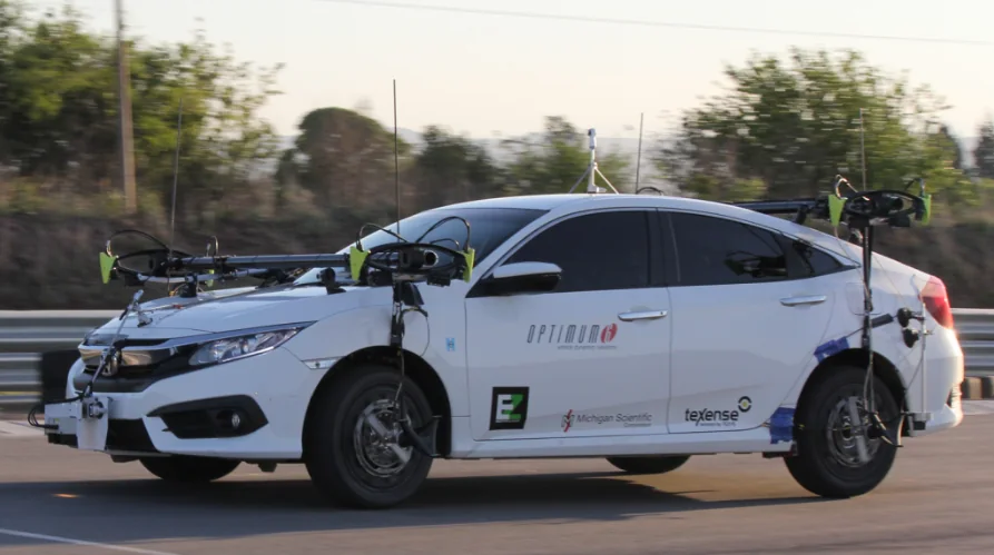 Dynamics Vehicle dynamics The forces and moments at each wheel while the vehicle brakes, turns and changes lane.
-
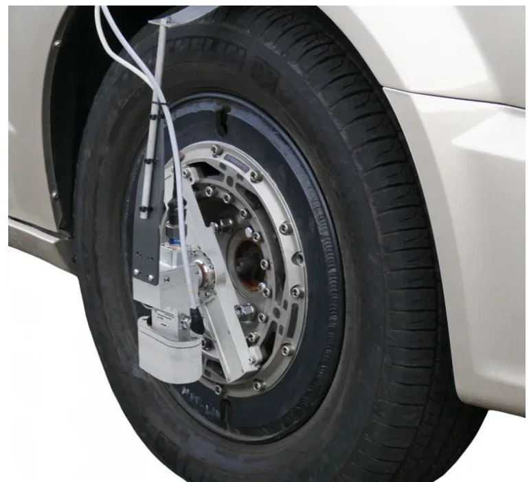 Dynamics Side slip angle Side slip angle read without contact by an optical sensor, on a wheel or on the vehicle body.
-
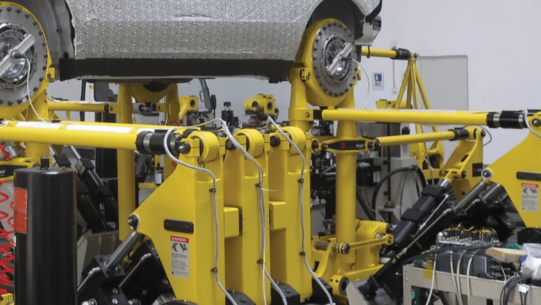 Test rig Road simulators The loads measured at the wheel on the road, and the proof that the simulator reproduces them.
If a six-axis wheel is not what you need
- Torque only TW series wheel torque transducers
Drive and brake torque My at the wheel, 237 N·m to 81 kN·m.
- Signals from the series wheel Wheel instrumentation system
Strain gages, thermocouples and wheel speed, on the wheel the vehicle already has.
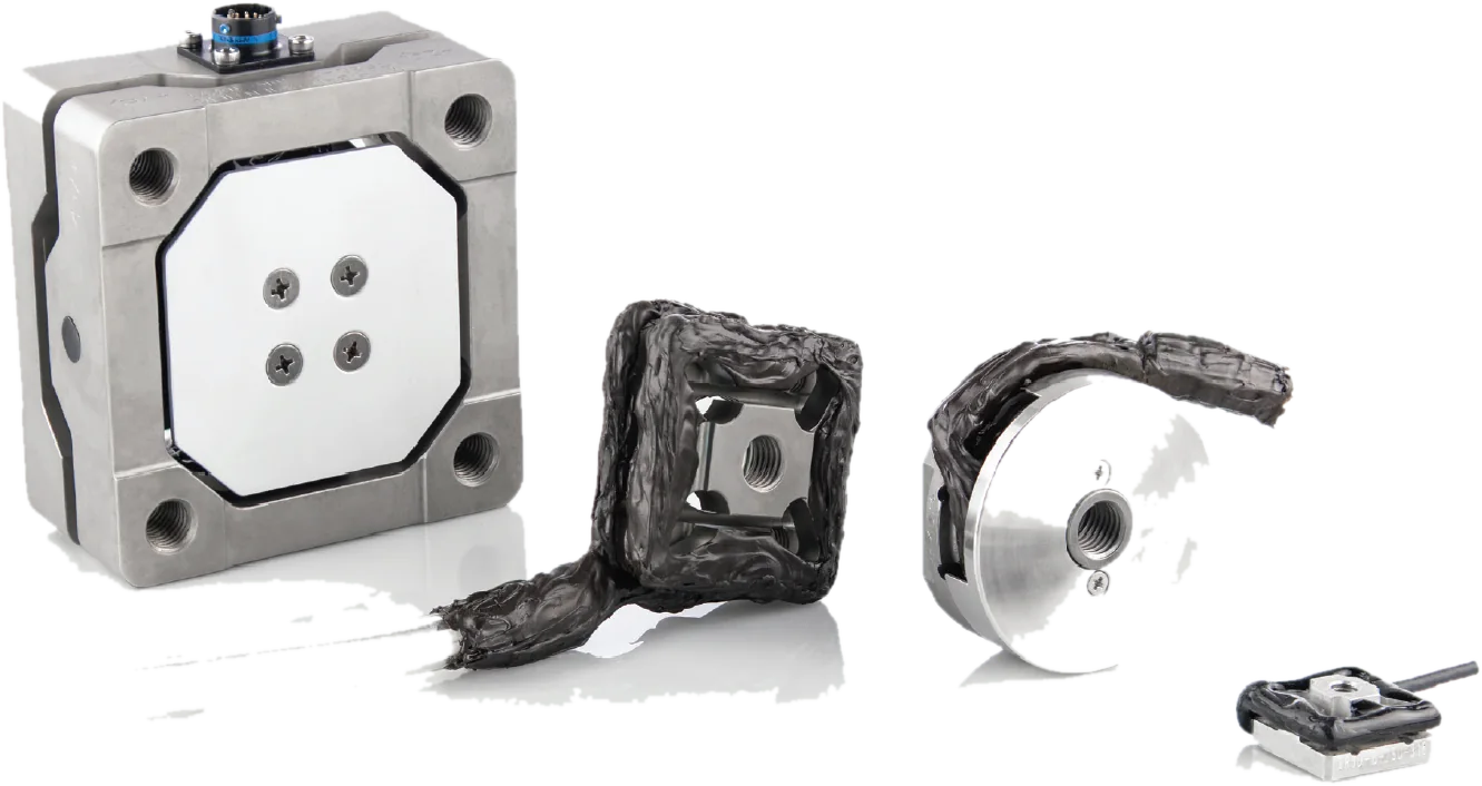
- Force on a part, not a wheel TR3D-B three-axis load cells
Three orthogonal forces from 1.1 to 71 kN per axis.
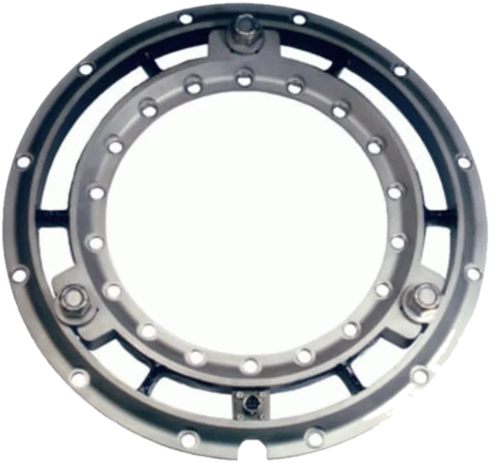
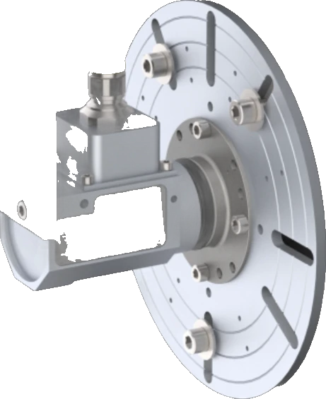
A question on this product?
Vehicle, wheel size, expected loads. An application engineer answers.
More details to give? Use the full contact form.