
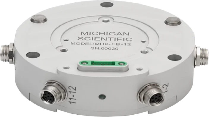
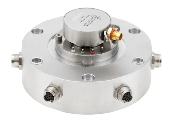
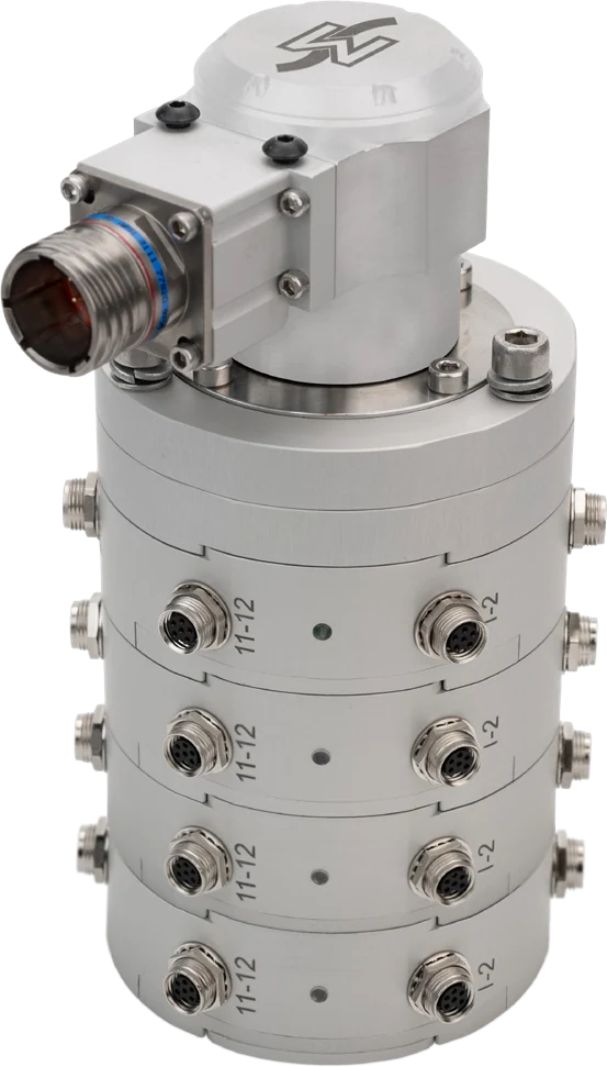
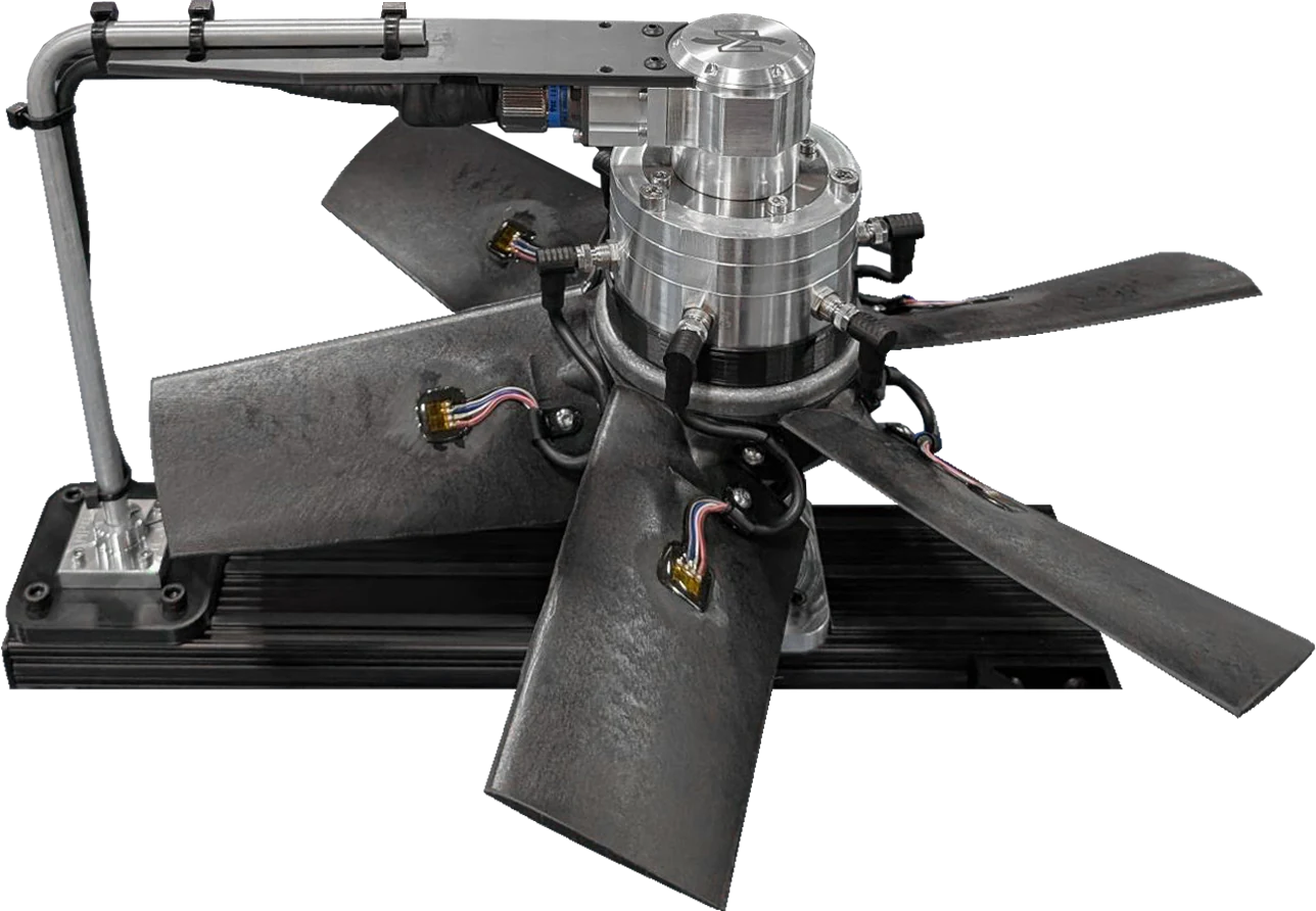
MUX-FB-12 twelve-channel analog to CAN module
Twelve-channel full-bridge strain gage amplifier: 4.5 V excitation, conditioning and 16-bit digitization onto one CAN 2.0 or CAN FD bus, up to 8 ksps.
Model MUX-FB-12
- 12
- Full-bridge channels
- 8 ksps
- Max output rate, CAN FD
- ± 36 mV
- Input range
- Ø 86 × 25.4 mm
- Housing
- OutputCAN 2.0 / CAN FD
- Max output rate8 ksps, CAN FD; 2 ksps, CAN 2.0
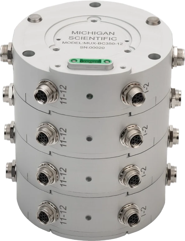
- StackingUp to 4 modules, 48 synchronized channels
- ConfigurationSoftware, per channel
MUX-FB-12: twelve full-bridge transducers onto one CAN bus
The MUX-FB-12 takes twelve full-bridge strain gage transducers in 4-wire connection, two per M8 8-pin connector. Each channel has its own amplifier: 4.5 V ratiometric excitation, ±36 mV input range with gain and bridge balance set by software, 16-bit digitization, and positive and negative shunt calibration through an integrated 100 kΩ resistor. Output: CAN 2.0 up to 2 ksps, CAN FD up to 8 ksps on all twelve channels, 1.6 kHz at −3 dB. Supply 10 to 36 V DC; −40 to 85 °C; IP67 with the stacking connectors.
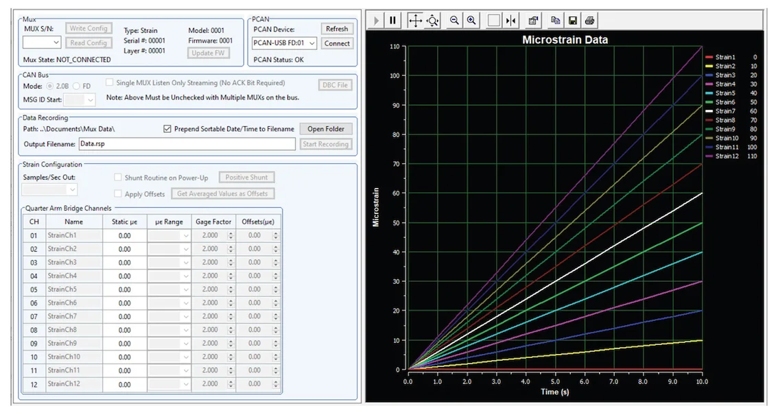
The module ships with its sensor cables, a setup cable for power and CAN, and the MUX Tool software for Windows. Over a PEAK-System USB-to-CAN adapter, the software configures each channel, records one module to a PC and generates the DBC file for a data recorder. Up to four modules stack, without cables between them, for 48 synchronized channels.
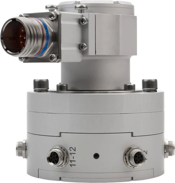
On a rotating part, the SR10AW/WFT slip ring and its 1024 ppr encoder mount on the stack through the MUX-ENC-ADA adapter layer; encoder position and speed come out with the module data. On a fixed part, the MUX-CON-ADA-NS adapter layer takes the power and data cable.
Specifications
| Channels | 12 (per module, stackable to 48 with four modules) |
|---|---|
| Input | Strain gage bridge (full bridge, 4-wire; input range ±36 mV) |
| Output | CAN · CAN FD |
| Bandwidth | 1.6 kHz (−3 dB; 0.5 kHz at −0.1 dB, 4 or 8 ksps output rate) |
| Sample rate | 8 kHz (12 channels, CAN FD at 4 Mbit/s; 2 kHz on CAN 2.0) |
| Noise, referred to input | ≤ 0.25 µV (p-p, 0.1 to 10 Hz; density about 12 nV/√Hz) |
| Gain setting | Software (per channel; PC software included for configuration and data recording) |
| Shunt calibration | Positive · Negative · Software (integrated; also at power-up) |
| Shunt resistor | 100 kΩ (up to 10 MΩ emulated) |
| Gain accuracy | ≤ 0.2 % |
| Gain temperature coefficient | ≤ 0.004 %/°C |
| Input offset | ≤ 50 µV |
| Offset drift | ≤ 0.5 µV/°C |
| Shunt accuracy | ≤ 0.075 % |
| Supply voltage | 10 to 36 V |
| Excitation voltage | 4.5 V (ratiometric) |
| Power consumption | 2 W (typical, at 12 V DC with 12 bridges) |
| Excitation current limit | 13 mA |
| Galvanic isolation | 200 V (channel to CAN and channel to power; not a safety isolation for high-voltage applications) |
| Dimensions | Ø 86 × 25.4 mm (housing) |
| Weight | 300 g (approx.) |
| Operating temperature | −40 to 85 °C |
| Protection | IP67 (with stacking connectors) |
| Connections | Connector (inputs: 6 × M8 8-pin, two bridges each; power and CAN through the stacking connector) |
Request a quote
Works with
- TR3D-AThree perpendicular forces from one round body, mounted on a single central thread.
- TR3D-BThree perpendicular forces from a square body, down to 25.4 mm a side.
- TR3D-CThree perpendicular forces in a rugged stainless steel body, the same bolt pattern on both faces.
- TR3D-DThree perpendicular forces up to 444 kN per axis, in a stainless steel body with a weatherproof connector.
- TR5D-B-5KSquare five-axis load cell in sealed stainless steel: Fx, Fy, Fz to 22 kN and two bending moments, Mx and My, to 815 N·m, 33.34 mm high.
- TR6D-CSquare six-axis load cells, sealed, with identical top and base bolt patterns: Fx, Fy, Fz, Mx, My and Mz, 71 to 178 kN and 1.4 to 9.5 kN·m.
- TR6D-FLow-profile six-axis load cells in sealed stainless steel: Fx, Fy, Fz, Mx, My and Mz, 12.5 to 45 kN and 370 N·m to 3.4 kN·m, 24 to 40 mm high.
Resources
Datasheets and manuals
Drawings
None for MUX-FB-12.
CAD models
None for MUX-FB-12.
A question on this product?
Describe the measurement. An application engineer answers.
More details to give? Use the full contact form.