
SGA multi-channel strain gage amplifiers
Strain gage amplifier box for Michigan Scientific multi-axis load cells, with 3, 6 or 12 channels: bridge excitation, shunt calibration and a ± 10 V output per channel.
- 3
- Channels
- 1
- Load cell inputs
- ± 10 V
- Output
- 9 to 36 V DC
- Supply voltage
- 6
- Channels
- 2
- Load cell inputs
- ± 10 V
- Output
- 9 to 36 V DC
- Supply voltage
- 12
- Channels
- 4
- Load cell inputs
- ± 10 V
- Output
- 9 to 36 V DC
- Supply voltage
- ModelsSGA3 · SGA6 · SGA12
- Bridge excitation± 5 V (10 V total)
- Frequency response, −3 dB7.5 kHz at gain 201
- Operating temperature0 to 70 °C
- ModelsSGA3 · SGA6 · SGA12
- Bridge excitation± 5 V (10 V total)
- Frequency response, −3 dB7.5 kHz at gain 201
- Operating temperature0 to 70 °C
- ModelsSGA3 · SGA6 · SGA12
- Bridge excitation± 5 V (10 V total)
- Frequency response, −3 dB7.5 kHz at gain 201
- Operating temperature0 to 70 °C
One box for one to four load cells
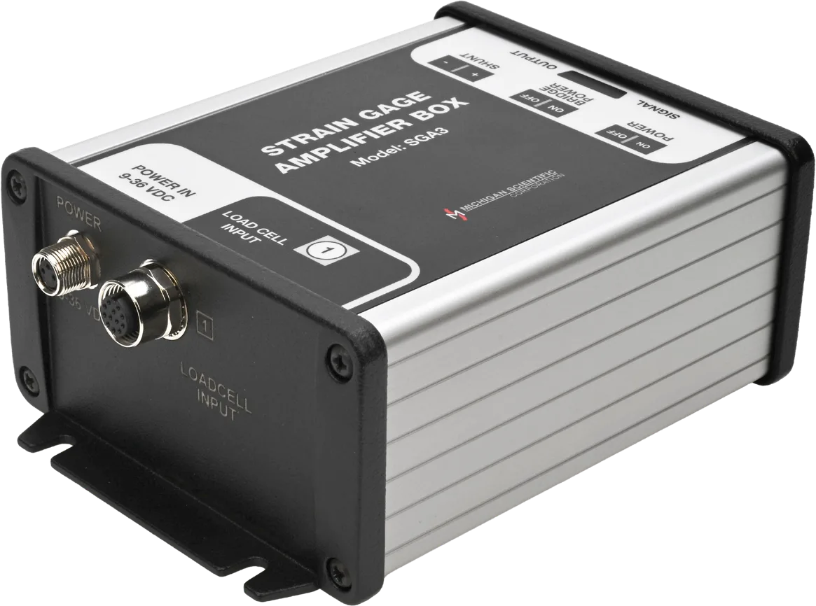
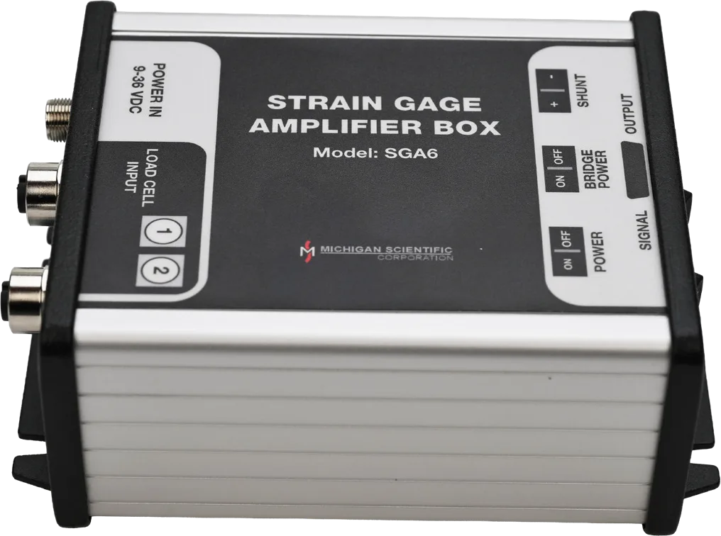
The SGA is a strain gage amplifier box for Michigan Scientific multi-axis load cells, built with 3, 6 or 12 channels: the SGA3 has one load cell input, the SGA6 two and the SGA12 four, each carrying the X, Y and Z bridges of a three-axis load cell. Each channel gets bipolar DC constant-voltage excitation of ± 5 V (10 V total), accurate to 0.10 %, a precision low-noise differential amplifier with a nominal gain of 201 V/V, and integrated 100 kΩ shunt resistors for positive and negative shunt calibration. Each output has a ± 10 V range and a −3 dB frequency response of 7.5 kHz. The box runs on 9 to 36 V DC and operates from 0 to 70 °C.
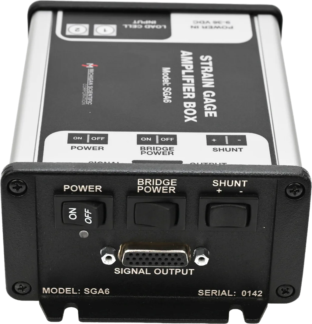
The load cells and the power cable plug into M12 connectors on the back panel. The outputs leave on the front panel through a 26-pin D-sub breakout cable, which bundles the signals of each load cell in its own wire group, labeled 1 to 4. Three switches sit on the front panel: power; bridge power, which turns the excitation on or off while the amplifier stays powered; and a momentary shunt switch, held in the positive or negative position to output the shunt voltage. Each load cell's sensitivities are on its calibration sheet; the no-load output is removed in the data acquisition system, by nulling the channels before recording or in post-processing.
It is used with one three-axis load cell to measure engine mount or pintle hitch forces, and with four cells to measure seat mounting forces or the net loads on a platform.
Specifications
| Channels | 3 |
|---|---|
| Input | Strain gage bridge (one load cell input, X, Y and Z) |
| Output | Analog voltage |
| Output range | −10 to 10 V |
| Bandwidth | 7.5 kHz (−3 dB at gain 201) |
| Gain | 201 V/V (nominal, default) |
| Shunt calibration | Positive · Negative · Manual switch (momentary switch on the front panel) |
| Shunt resistor | 100 kΩ |
| Gain accuracy | ≤ 0.1 % (typical, at 25 °C and gain 201) |
| Gain temperature coefficient | ≤ 0.0025 %/°C |
| Input offset | ≤ 25 µV |
| Offset drift | ≤ 0.2 µV/°C |
| Shunt accuracy | ≤ 0.01 % |
| Supply voltage | 9 to 36 V (DC) |
| Excitation voltage | 10 V (± 5 V, bipolar DC constant voltage; on/off switch) |
| Bridge resistance | 350 Ω (minimum) |
| Supply current | 1.25 A |
| Excitation accuracy | ≤ 0.1 % |
| Excitation temperature coefficient | ≤ 0.0005 %/°C |
| Dimensions | 160 × 108 × 58.6 mm |
| Operating temperature | 0 to 70 °C |
| Connections | Connector (power: M12 A-coded · load cells: M12 A-coded, 12 pins · outputs: 26-pin D-sub with breakout cable) |
| Channels | 6 |
|---|---|
| Input | Strain gage bridge (two load cell inputs, X, Y and Z each) |
| Output | Analog voltage |
| Output range | −10 to 10 V |
| Bandwidth | 7.5 kHz (−3 dB at gain 201) |
| Gain | 201 V/V (nominal, default) |
| Shunt calibration | Positive · Negative · Manual switch (momentary switch on the front panel) |
| Shunt resistor | 100 kΩ |
| Gain accuracy | ≤ 0.1 % (typical, at 25 °C and gain 201) |
| Gain temperature coefficient | ≤ 0.0025 %/°C |
| Input offset | ≤ 25 µV |
| Offset drift | ≤ 0.2 µV/°C |
| Shunt accuracy | ≤ 0.01 % |
| Supply voltage | 9 to 36 V (DC) |
| Excitation voltage | 10 V (± 5 V, bipolar DC constant voltage; on/off switch) |
| Bridge resistance | 350 Ω (minimum) |
| Supply current | 1.25 A |
| Excitation accuracy | ≤ 0.1 % |
| Excitation temperature coefficient | ≤ 0.0005 %/°C |
| Dimensions | 160 × 108 × 58.6 mm |
| Operating temperature | 0 to 70 °C |
| Connections | Connector (power: M12 A-coded · load cells: M12 A-coded, 12 pins · outputs: 26-pin D-sub with breakout cable) |
| Channels | 12 |
|---|---|
| Input | Strain gage bridge (four load cell inputs, X, Y and Z each) |
| Output | Analog voltage |
| Output range | −10 to 10 V |
| Bandwidth | 7.5 kHz (−3 dB at gain 201) |
| Gain | 201 V/V (nominal, default) |
| Shunt calibration | Positive · Negative · Manual switch (momentary switch on the front panel) |
| Shunt resistor | 100 kΩ |
| Gain accuracy | ≤ 0.1 % (typical, at 25 °C and gain 201) |
| Gain temperature coefficient | ≤ 0.0025 %/°C |
| Input offset | ≤ 25 µV |
| Offset drift | ≤ 0.2 µV/°C |
| Shunt accuracy | ≤ 0.01 % |
| Supply voltage | 9 to 36 V (DC) |
| Excitation voltage | 10 V (± 5 V, bipolar DC constant voltage; on/off switch) |
| Bridge resistance | 350 Ω (minimum) |
| Supply current | 1.25 A |
| Excitation accuracy | ≤ 0.1 % |
| Excitation temperature coefficient | ≤ 0.0005 %/°C |
| Dimensions | 160 × 108 × 58.6 mm |
| Operating temperature | 0 to 70 °C |
| Connections | Connector (power: M12 A-coded · load cells: M12 A-coded, 12 pins · outputs: 26-pin D-sub with breakout cable) |
Request a quote
Works with
- TR3D-AThree perpendicular forces from one round body, mounted on a single central thread.
- TR3D-BThree perpendicular forces from a square body, down to 25.4 mm a side.
- TR3D-CThree perpendicular forces in a rugged stainless steel body, the same bolt pattern on both faces.
- TR3D-DThree perpendicular forces up to 444 kN per axis, in a stainless steel body with a weatherproof connector.
- TR5D-B-5KSquare five-axis load cell in sealed stainless steel: Fx, Fy, Fz to 22 kN and two bending moments, Mx and My, to 815 N·m, 33.34 mm high.
- TR6D-CSquare six-axis load cells, sealed, with identical top and base bolt patterns: Fx, Fy, Fz, Mx, My and Mz, 71 to 178 kN and 1.4 to 9.5 kN·m.
- TR6D-FLow-profile six-axis load cells in sealed stainless steel: Fx, Fy, Fz, Mx, My and Mz, 12.5 to 45 kN and 370 N·m to 3.4 kN·m, 24 to 40 mm high.
Resources
Datasheets and manuals
Drawings
None for this product.
CAD models
None for this product.
Related applications
-
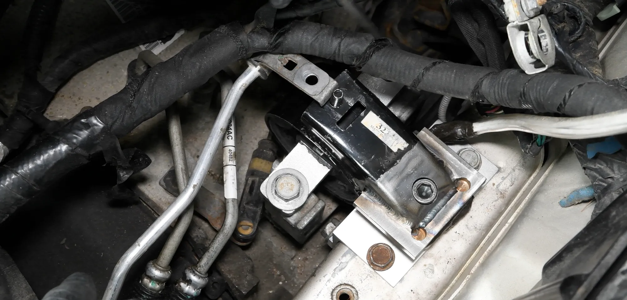 Component Engine mount loads The three forces each mount passes to the frame during start-up, acceleration and gear shifts.
-
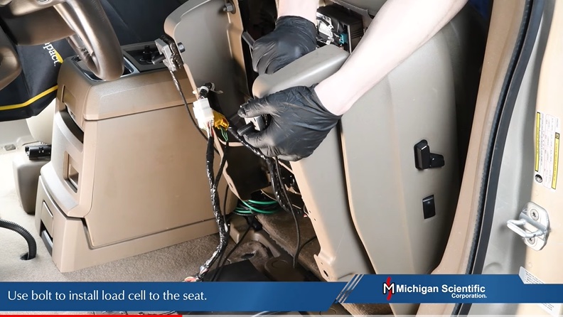 Component Seat forces Fx, Fy and Fz at each seat mounting, while driving and in a crash, with the seat at its production height.
-
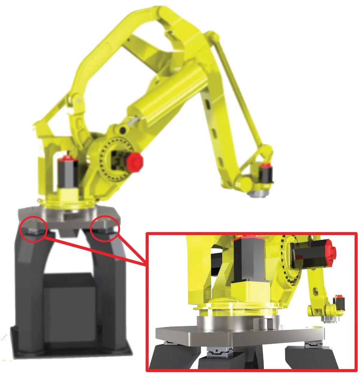 Component Robotics and prosthetics Forces in three directions, and moments, on a robot arm or a prosthetic foot, from a load cell small enough to fit in the assembly.
-
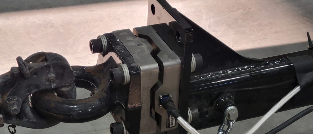 Towing Pintle hitch forces The three forces between towing vehicle and trailer, recorded in real towing situations.
A question on this product?
Describe the measurement. An application engineer answers.
More details to give? Use the full contact form.