
TR6D-C - Rugged six-axis load cells for durability testing
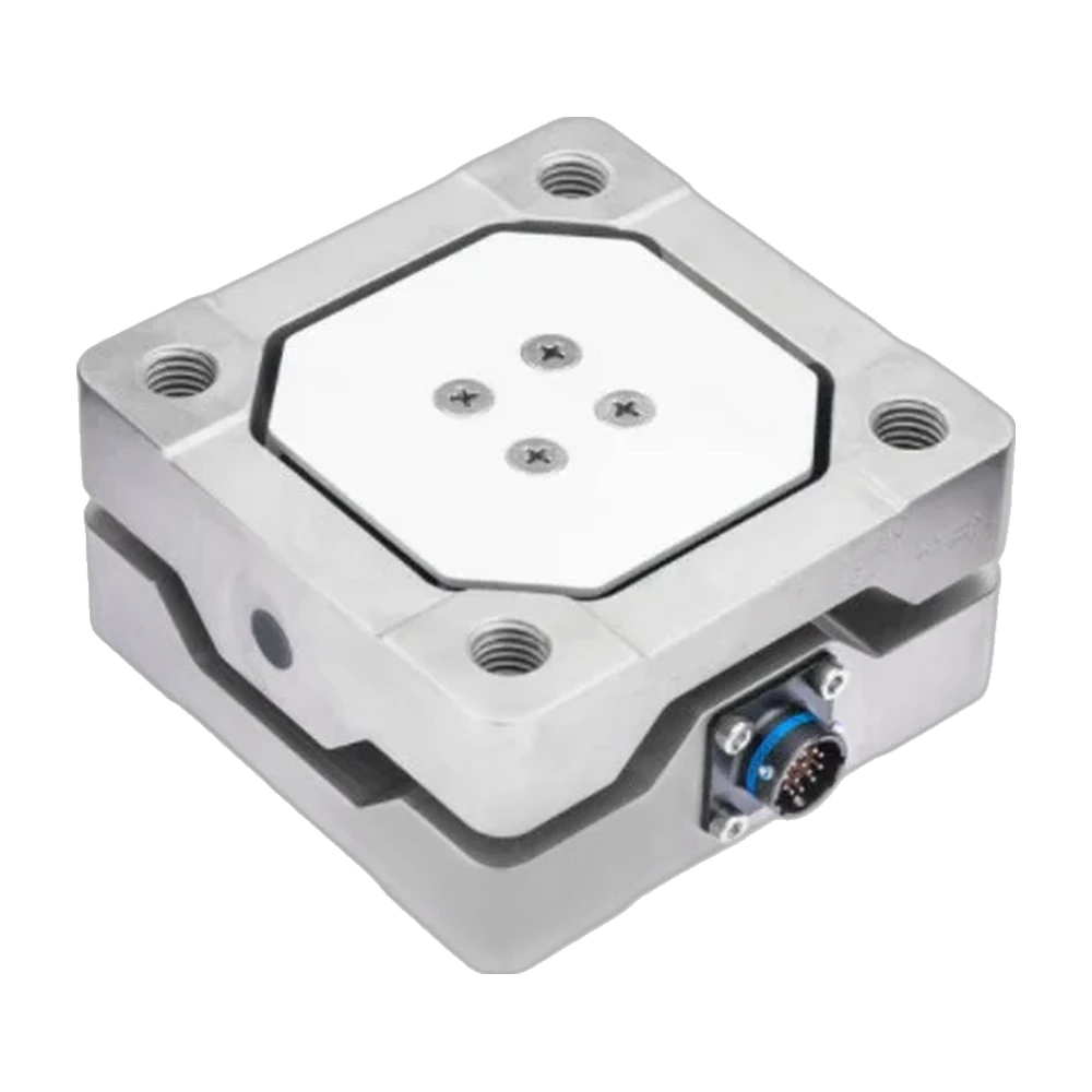
Square six-axis load cells, sealed, with identical top and base bolt patterns: Fx, Fy, Fz, Mx, My and Mz, 71 to 178 kN and 1.4 to 9.5 kN·m.
- 71 kN
- Force capacity, Fx, Fy, Fz
- 1.4 kN·m
- Moment capacity, Mx, My, Mz
- 101.6 × 101.6 × 50.8 mm
- Dimensions
- 2.2 kg
- Weight
- 89 kN
- Force capacity, Fx, Fy, Fz
- 4.5 kN·m
- Moment capacity, Mx, My, Mz
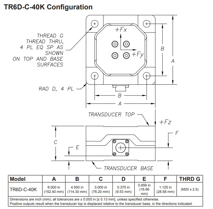
- 152.4 × 152.4 × 76.2 mm
- Dimensions
- 4.3 kg
- Weight
- 178 kN
- Force capacity, Fx, Fy, Fz
- 9.5 kN·m
- Moment capacity, Mx, My, Mz
- 152.4 × 152.4 × 76.2 mm
- Dimensions
- 7.5 kg
- Weight
- ModelsTR6D-C-16K · TR6D-C-20K · TR6D-C-40K
- Mounting4 through threads, top and base
- Cable3.05 m, shielded, open-ended leads
Same bolt pattern, top and base
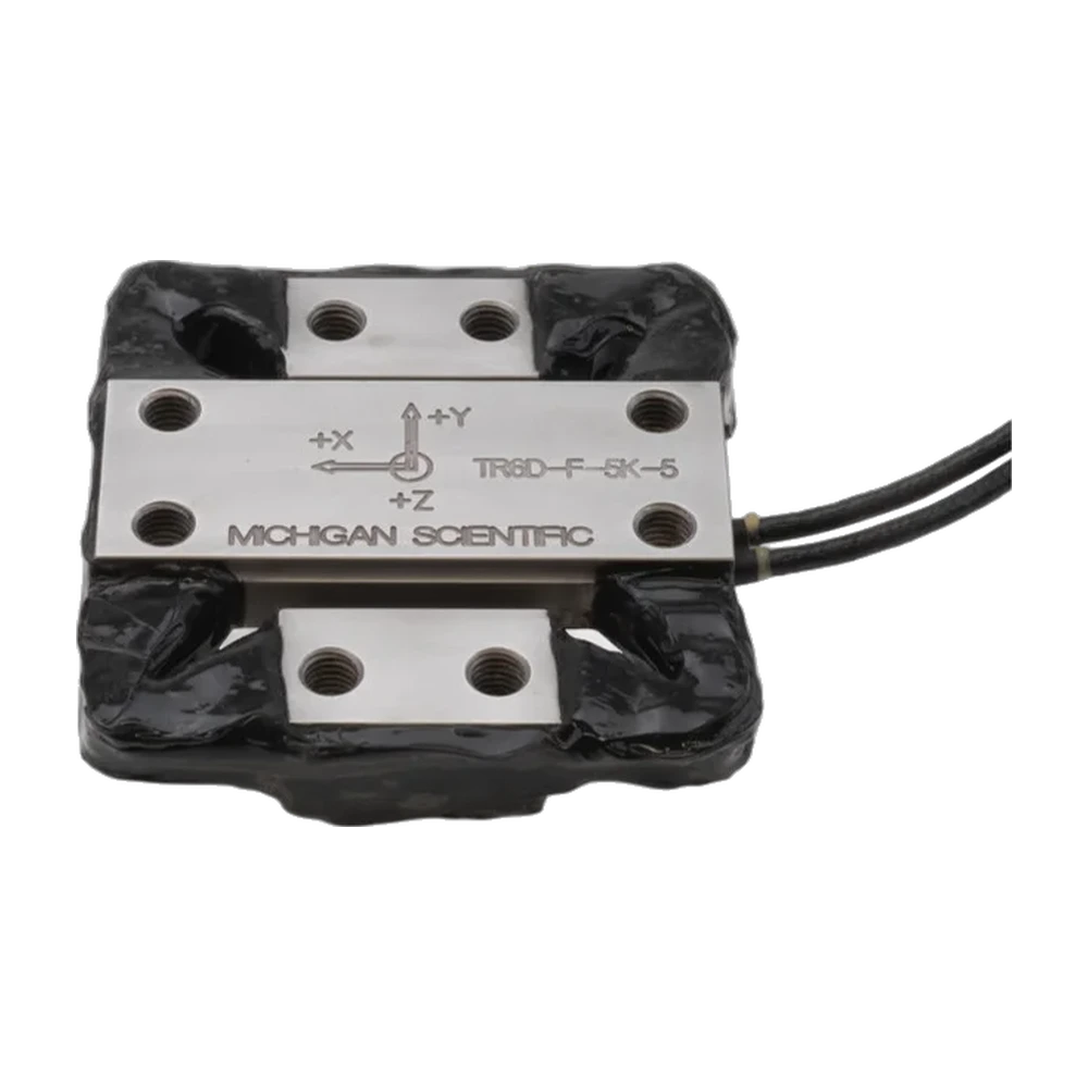
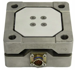
The TR6D-C is a square six-axis load cell. It measures three forces, Fx, Fy and Fz, and three moments, Mx, My and Mz, with six four-arm strain gage bridges. Three models: the TR6D-C-16K, 71 kN and 1.4 kN·m, stainless steel, 101.6 mm square and 50.8 mm high, 2.2 kg; the TR6D-C-20K, 89 kN and 4.5 kN·m, titanium, 152.4 mm square and 76.2 mm high, 4.3 kg; the TR6D-C-40K, 178 kN and 9.5 kN·m, stainless steel, same size as the 20K, 7.5 kg. The body is sealed against the weather and temperature compensated, usable from −40 to 149 °C.
The top and base faces and their bolt patterns are identical: four threads, M12 × 1.75 on the TR6D-C-16K, M20 × 2.5 on the 20K and 40K, run through the cell and take the load from either face. Positive outputs result when the top is displaced relative to the base in the directions shown on the drawing. Excitation is 10 V DC or AC rms maximum. The cell has a weatherproof connector; the standard cable is 3.05 m, shielded, with open-ended leads. Individual bridge connectors and cable length are specified at order. Each cell ships with an ISO/IEC 17025 calibration report, which includes the crosstalk matrix.
The TR6D-C is built for field data acquisition and for laboratory testing.
Specifications
| Measured quantities | Fx · Fy · Fz · Mx · My · Mz |
|---|---|
| Force capacity | Fx 71 · Fy 71 · Fz 71 kN |
| Moment capacity | Mx 1 400 · My 1 400 · Mz 1 400 N·m |
| Overload capacity | 20 % |
| Non-linearity | Fx ≤ 1 · Fy ≤ 1 · Fz ≤ 2 · Mx ≤ 0.5 · My ≤ 0.5 · Mz ≤ 0.5 % FS |
| Hysteresis | Fx ≤ 2 · Fy ≤ 2 · Fz ≤ 4 · Mx ≤ 1 · My ≤ 1 · Mz ≤ 1 % FS |
| Axes | 6 |
| Sensing principle | Strain gage |
| Load direction | Tension · Compression |
| Calibration | ISO 17025 (calibration report with crosstalk matrix) |
| Rated output | Fx 0.5 · Fy 0.5 · Fz 0.5 · Mx 3 · My 3 · Mz 0.8 mV/V (nominal) |
| Excitation voltage | 10 V (max, DC or AC rms) |
| Mounting fasteners | 4 × M12 × 1.75 (threaded through, used from the top and from the base) |
| Dimensions | 101.6 × 101.6 × 50.8 mm |
| Weight | 2.2 kg |
| Material | Stainless steel |
| Operating temperature | −40 to 149 °C |
| Protection | Weatherproof (sealed) |
| Connections | Connector · Cable (weatherproof connector on the cell · shielded cable, open-ended leads) |
| Cable length | 3.05 m |
| Measured quantities | Fx · Fy · Fz · Mx · My · Mz |
|---|---|
| Force capacity | Fx 89 · Fy 89 · Fz 89 kN |
| Moment capacity | Mx 4 500 · My 4 500 · Mz 4 500 N·m |
| Overload capacity | 20 % |
| Non-linearity | Fx ≤ 0.5 · Fy ≤ 0.5 · Fz ≤ 1.5 · Mx ≤ 0.5 · My ≤ 0.5 · Mz ≤ 0.5 % FS |
| Hysteresis | ≤ 0.5 % FS |
| Axes | 6 |
| Sensing principle | Strain gage |
| Load direction | Tension · Compression |
| Calibration | ISO 17025 (calibration report with crosstalk matrix) |
| Rated output | Fx 1.5 · Fy 1.5 · Fz 1.5 · Mx 5 · My 5 · Mz 1.75 mV/V (nominal) |
| Excitation voltage | 10 V (max, DC or AC rms) |
| Mounting fasteners | 4 × M20 × 2.5 (threaded through, used from the top and from the base) |
| Dimensions | 152.4 × 152.4 × 76.2 mm |
| Weight | 4.3 kg |
| Material | Titanium |
| Operating temperature | −40 to 149 °C |
| Protection | Weatherproof (sealed) |
| Connections | Connector · Cable (weatherproof connector on the cell · shielded cable, open-ended leads) |
| Cable length | 3.05 m |
| Measured quantities | Fx · Fy · Fz · Mx · My · Mz |
|---|---|
| Force capacity | Fx 178 · Fy 178 · Fz 178 kN |
| Moment capacity | Mx 9 500 · My 9 500 · Mz 9 500 N·m |
| Non-linearity | Fx ≤ 0.5 · Fy ≤ 0.5 · Fz ≤ 1.5 · Mx ≤ 0.5 · My ≤ 0.5 · Mz ≤ 0.5 % FS |
| Hysteresis | ≤ 0.5 % FS |
| Axes | 6 |
| Calibration | ISO 17025 (calibration report with crosstalk matrix) |
| Rated output | Fx 1.5 · Fy 1.5 · Fz 1.5 · Mx 5 · My 5 · Mz 1.75 mV/V (nominal) |
| Excitation voltage | 10 V (max, DC or AC rms) |
| Mounting fasteners | 4 × M20 × 2.5 (threaded through, used from the top and from the base) |
| Dimensions | 152.4 × 152.4 × 76.2 mm |
| Weight | 7.5 kg |
| Material | Stainless steel |
| Operating temperature | −40 to 149 °C |
| Protection | Weatherproof (sealed) |
| Connections | Connector · Cable (weatherproof connector on the cell · shielded cable, open-ended leads) |
| Cable length | 3.05 m |
Used with the TR6D-C
What you add here goes into the same quote request.
-
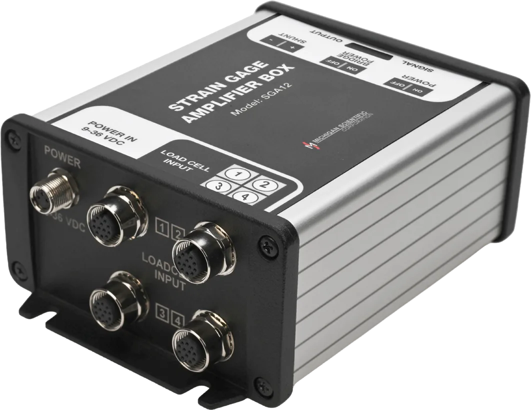
Read each axis as ± 10 V
SGA6, the six-channel model of the SGA series
± 5 V bridge excitation, a ± 10 V output per channel and shunt calibration from a switch on the box.
One SGA6 per load cell.
-
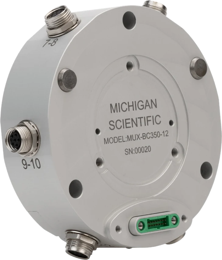
Log every axis on one CAN bus
MUX-FB-12, the full-bridge module of the MUX-12 series
Twelve full-bridge inputs, one CAN 2.0 or CAN FD output up to 8 ksps, integrated shunt resistors for calibration.
Twelve channels per module; up to four modules stack for 48 synchronized channels.
Resources
Datasheets and manuals
Drawings
None for this product.
CAD models
None for this product.
Guides and notes
Related applications
-
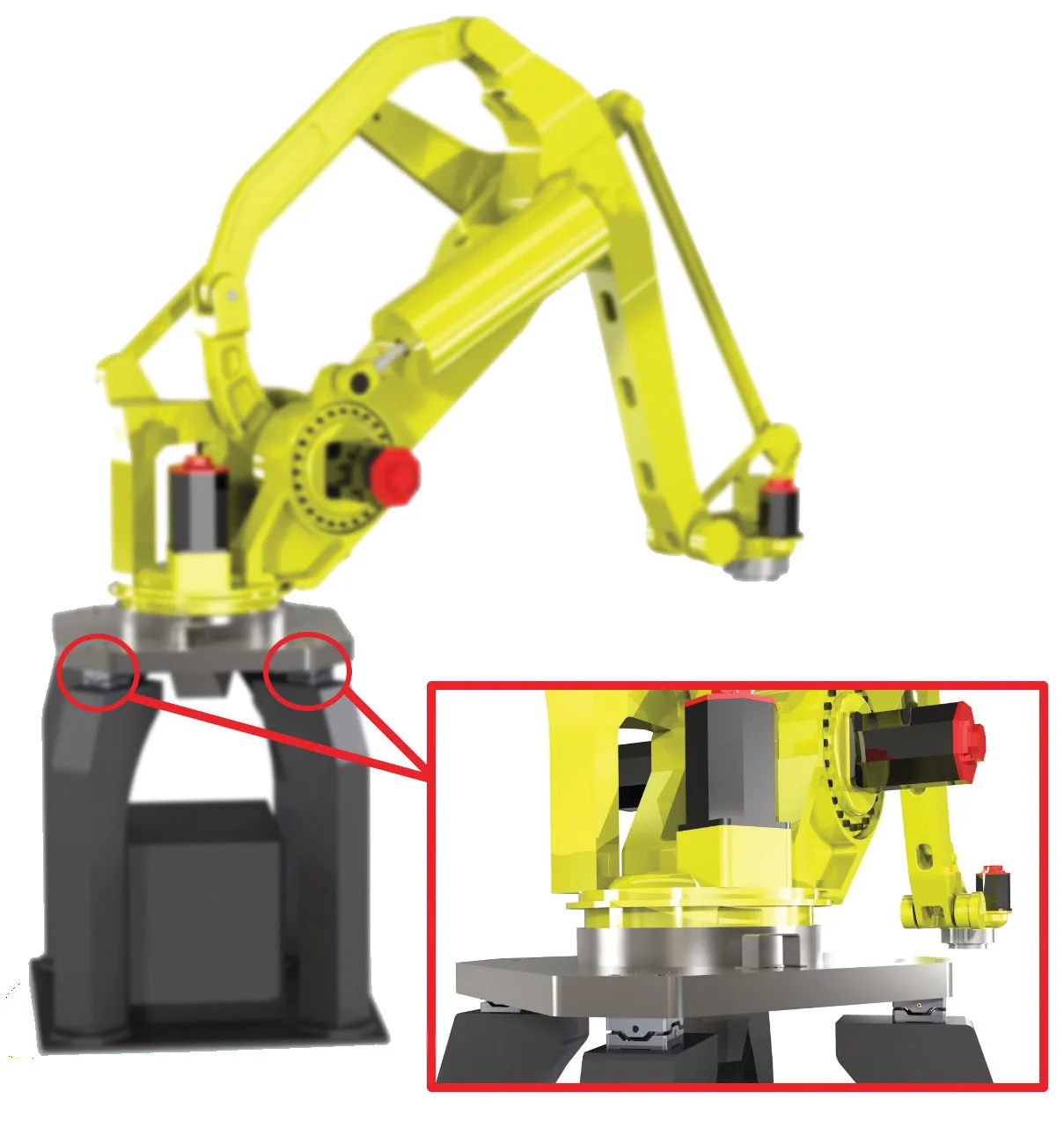 Component Robotics and prosthetics Forces in three directions, and moments, on a robot arm or a prosthetic foot, from a load cell small enough to fit in the assembly.
-
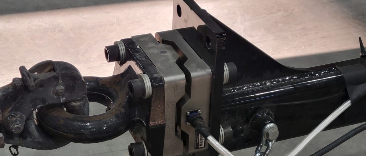 Towing Pintle hitch forces The three forces between towing vehicle and trailer, recorded in real towing situations.
-
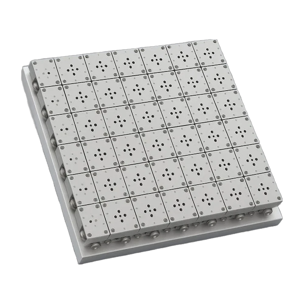
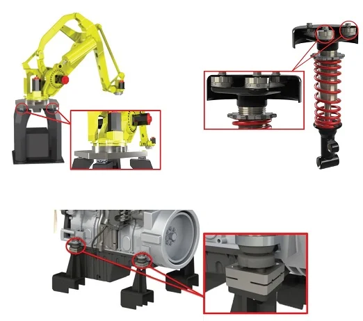 Rig Force and moment load platform Net forces and net moments on a system, calculated from four three-axis load cells.
-
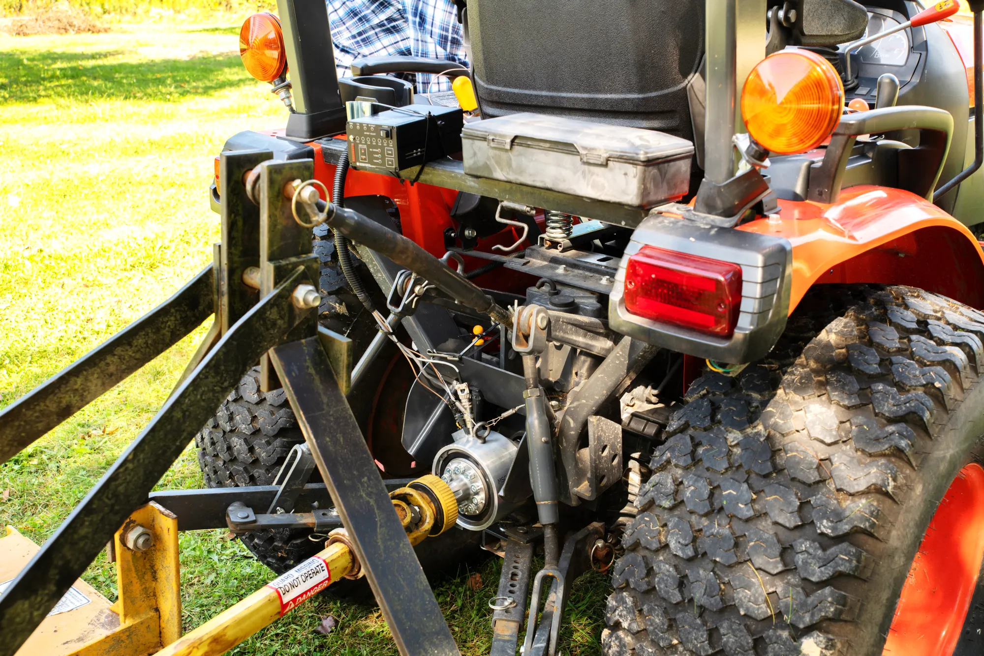 Agriculture PTO torque and power The torque and speed that the tractor delivers to the implement, measured during real field work.
In the same family
- Lower loads, less height TR6D-F
Low-profile six-axis load cells in sealed stainless steel: Fx, Fy, Fz, Mx, My and Mz, 12.5 to 45 kN and 370 N·m to 3.4 kN·m, 24 to 40 mm high.
- Crash and impact CT500
Three-axis crash barrier load cell, 500 kN on the impact axis and 125 kN across it, in a 124 mm stainless steel block that assembles into a barrier face.
- Three forces, square body TR3D-C
Three perpendicular forces in a rugged stainless steel body, the same bolt pattern on both faces.
A question on this product?
Describe the measurement. An application engineer answers.
More details to give? Use the full contact form.